Hyundai Elantra: Rear Corner Radar System / Rear Corner Radar Unit
Hyundai Elantra (CN7) 2021-2025 Service Manual / Advanced Driver Assistance System (ADAS) / Rear Corner Radar System / Rear Corner Radar Unit
Specifications
| Specifications |
|
Items
|
Blind-Spot Collision Warning (BCW)
|
Blind-Spot Collision- Avoidance Assist-Rear (BCA-R)
|
| Rated voltage | DC 12V | |
| Operating voltage | 9V - 16V | |
| Operating speed | 30 km/h - 255 km/h | 60 km/h - 180 km/h |
| Sensible distance | 70m | |
| Curvature radius | Start : More than 100m | Start : More than 625m |
| Stop : Less than 70m | Stop : Less than 588m | |
| Frequency | 24 GHz | |
| Numbers | 2EA | |
|
Items
|
Rear Cross-Traffic Collision Warning (RCCW)
|
Rear Cross-Traffic Collision- Avoidance Assist (RCCA)
|
| Rated voltage | DC 12V | |
| Operating voltage | 9V - 16V | |
| Operating speed | 0 km/h - 10 km/h | 1 km/h - 10 km/h |
| Sensible distance | 25m | |
| Curvature radius | - | |
| Frequency | 24 GHz | |
| Numbers | 2EA | |
|
Items
|
Safe Exit Assist (SEA)
|
| Rated voltage | DC 12V |
| Operating voltage | 9V - 16V |
| Operating speed | 0 km/h - 3 km/h |
| Sensible distance | 25m |
| Curvature radius | - |
| Frequency | 24GHz |
| Numbers | 2EA |
Schematic diagrams
| Connector and Terminal Function |
|
Pin
|
Function
|
| 1 | L-CAN High |
| 2 | C-CAN High |
| 3 | - |
| 4 | Battery (+) |
| 5 | Ground |
| 6 | L-CAN Low |
| 7 | C-CAN Low |
| 8 | Warning indicator |
| Circuit Diagram |
Repair procedures
| Removal |
lf replacement of the rear corner radar unit bracket or extension wire is required, replace the defective part only with a new one. |

| 1. | Disconnect the negative (-) battery terminal. |
| 2. | Remove the rear bumper assembly. (Refer to Body - "Rear Bumper Assembly") |
| 3. | Disconnect the rear corner radar unit connector (A).
|
| 4. | Loosen the mounting screws and remove the rear corner radar lower bracket (A).
|
| 5. | Loosen the mounting screws and remove the rear corner radar unit (A).
|
| Installation |
| 1. | Install the blind spot radar unit and bracket.
|
| 2. | Install the rear bumper. |
| 3. | Connect the negative (-) battery terminal.
|
| 4. | Perform "Correcting the Blind-Spot Radar Unit Angle" procedures. |
| 5. | Perform "BSD Radar Calibration" procedures. |
| Adjustment |
Correcting the Blind-Spot Radar Unit Angle
| 1. | After replacing the blind-spot radar unit or bracket, with the bumper removed, use the blind-spot radar unit correction tool set (special tool : 09985-3T500) to perform angle correction.
|


| 2. | Attach a vertical plumb (special tool : 09958-3T010) on the hood, and lower the plumb (A) to the ground so that it passes through the center of the emblem.
|
| 3. | Marking the center point below the plumb (A).
|
| 4. | Attach a vertical plumb (special tool : 09958-3T010) on the trunk (or tailgate), and lower the plumb (A) to the ground so that it passes through the center of the emblem.
|
| 5. | Marking the center point below the plumb (A).
|
| 6. | Marking the center of vehicle by a string.
|
| 7. | Mount the blind-spot radar unit fixing adaptor (special tool : 09958-3T080) on the blind-spot radar unit and fix the level laser (special tool : 09958-3T070).
|
| 8. | Measure the angle (C) between the center line (A) of the angle measuring plate and the horizontal laser beam (B) using a digital protractor (special tool : 09958-3T090).
|
| 9. | Use a digital inclinometer (special tool : 09958-3T100) to measure the vertical angle of the blind-spot radar unit.
|
| 10. | Measure the horizontal and vertical angles of left and right blind-spot radar units. If the measured values deviate from the specified values, insert a washer between the bracket of the blind-spot radar unit.
|
| 11. | After checking and correcting the blind-spot radar unit angle, perform the blind-spot radar radar correction procedure. |
Diagnosis with Diagnostic tool
| 1. | Rear bumper accident vehicles and vehicles that replaced BCW units must perform BCW unit alignment using Diagnostic tool. |
| 2. | Connect the cable of Diagnostic tool to the data link connector in driver side crash pad lower panel, and turn on the Diagnostic tool. |
| 3. | Select the 'S/W Management' and 'Car model'.
|
| 4. | Select "Blind -Spot Collision Warning" and "BSD Radar Calibration".
|
| 5. | Perform the "BSD Radar Calibration" procedure according to the Diagnostic tool screen message.
|

 Warning Indicator
Components and components location
Components1. BSD Indicator2. Side repeater lamp
Repair procedures
Inspection1.Disconnect the negative (-) battery terminal...
Other information:
Hyundai Elantra (CN7) 2021-2025 Service Manual: Intake Manifold
Components and components location Components1. Electronic throttle body (ETC)2. Return hose3. Return pipe4. Intake manifold5. Intake manifold gasket Repair procedures Removal and Installation1.Disconnect the battery negative terminal.2.Remove the engine cover...
Hyundai Elantra (CN7) 2021-2025 Service Manual: High Mounted Stop Lamp
Repair procedures Removal1.Disconnect the negative (-) battery terminal.2.Remove the rear package tray trim.(Refer to Body - "Rear Package Tray Trim")3.Loosen the mounting screws and remove the high mounted stop lamp (A).Installation1.Install the high mounted stop lamp...
Categories
- Manuals Home
- 7th Gen Hyundai Elantra Owners Manual
- 7nd Gen Hyundai Elantra Service Manual
- Control Cable
- Integrated Thermal Management Module (ITM)
- Forward Collision–Avoidance Assist (FCA) (sensor fusion)
- Maintenance
- System disabled
Air bag collision sensors
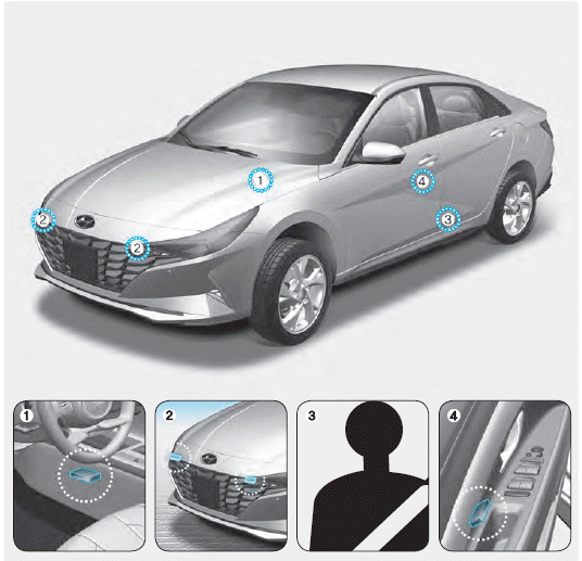
1. SRS control module/Rollover sensor
2. Front impact sensors
3. Side impact sensors (acceleration)
4. Side impact sensors (pressure)

Copyright © 2025 www.helantra7.com