Hyundai Elantra (CN7): SRSCM / Side Impact Sensor (SIS)
Description and operation
| Description |
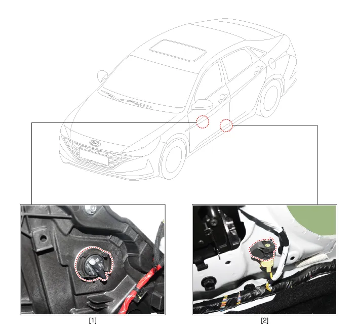
| ŌĆó | Side Impact Sensors (SIS), each installed on the center part of the right and left front door modules and the right and left center pillars, detects side impact during collision. |
| ŌĆó | The pressure-sensitive side collision detection sensor (P-SIS) is a method that senses the pressure when it collides, and is also called P-SIS, and the side collision detection sensor (G-SIS) is a method that senses the acceleration at the time of collision. Also called G-SIS. |
| ŌĆó | The SRSCM uses the signals from SIS during side collision to determine whether and when to deploy the side air bag. |
Components and components location
| Components |
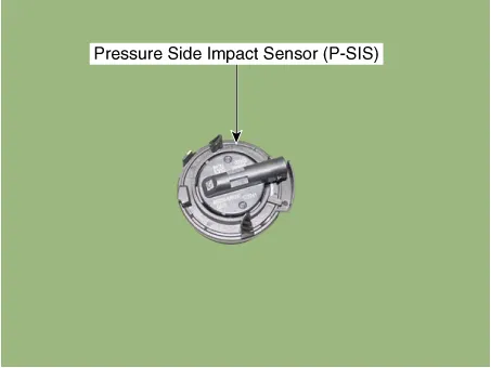
| 1. Pressure Side Impact Sensor (P-SIS) | 2. Gravity Side Impact Sensor (G-SIS) |
Repair procedures
| Removal |
| 1. | Disconnect the negative (-) battery terminal.
|

| 2. | Remove the front door trim. (Refer to Body - "Front Door Trim") |
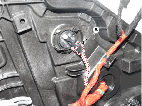
| 3. | Disconnect the pressure side impact sensor connector (A) after pushing the lock pin.
|
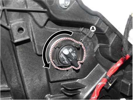
| 4. | Remove the pressure side impact sensor (A) after rotating it in the direction of the arrow.
|
| 1. | Disconnect the negative (-) battery terminal.
|
| 2. | Remove the center pillar trim. (Refer to Body (Interior and Exterior) - "Center Pillar Trim") |
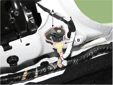
| 3. | Remove the gravity side impact sensor (A) after loosening the mounting bolt and disconnecting the connector (B).
|
| Installation |
| 1. | Check if the battery (-) cable is disconnected.
|
| 2. | Install a new pressure side impact sensor and connect the pressure side impact sensor connector. |
| 3. | Install the front door trim. (Refer to Body - "Front Door Trim") |
| 4. | Reconnect the battery negative (-) terminal. |
| 5. | After installing the front impact sensor, confirm proper system operation.
|


| 1. | Check if the battery (-) cable is disconnected.
|
| 2. | Install the new side impact sensor with the screws, then connect the front side impact sensor connector.
|
| 3. | Install the center pillar trim. (Refer to Body (Interior and Exterior) - "Center Pillar Trim") |
| 4. | Reconnect the battery negative (-) terminal.
|
Description and operation DescriptionThe front impact sensor (FIS) is installed in the Front End Module (FEM). They are remote sensors that detect acceleration due to a collision at its mounting location.
Description and operation DescriptionŌĆó The SRSCM should detect the condition of seat belt buckles (BS) of the driver and passenger seats.
Other information:
Hyundai Elantra (CN7) 2021-2026 Service Manual: Rear Combination Lamp
Repair procedures RemovalOutside Combination Lamp1.Disconnect the negative (-) battery terminal.2.Remove the combination lamp cover (A).3.Disconnect the rear combination lamp connector (A).4.Loosen the mounting nuts and remove the rear conbination lamp (A).
Hyundai Elantra (CN7) 2021-2026 Service Manual: Auto Lighting Control System
Description and operation DescriptionIt's a system that uses illumination sensor to automatically turn ON the tail lamp and head lamp based on the change in surrounding environment's illumination condition. It activates when the vehicle enters/exits tunnel, or when the illumination condition in surrounding environment changes due to rain, snow, or
Categories
- Manuals Home
- Hyundai Elantra Owners Manual
- Hyundai Elantra Service Manual
- Vehicle Information
- Body Electrical System
- Instrument Panel Overview
- New on site
- Most important about car
