Hyundai Elantra (CN7): Driver Parking Assistance System / ADAS Parking ECU (ADAS_PRK)
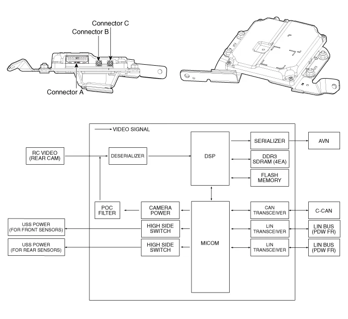
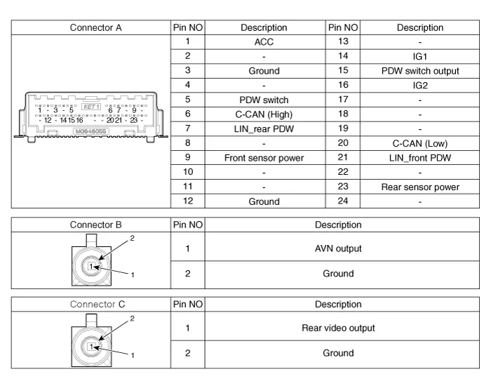
Components and components location
| Components and Components Location |
Repair procedures
| Removal |
|

| 1. | Disconnect the negative (-) battery terminal. |
| 2. | Remove the AVN Head unit. (Refer to Body Electrical System - "AVN Head Unit") |
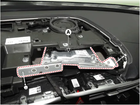
| 3. | Loosen the mounting screws and remove the ADAS_PRK Unit (A).
|
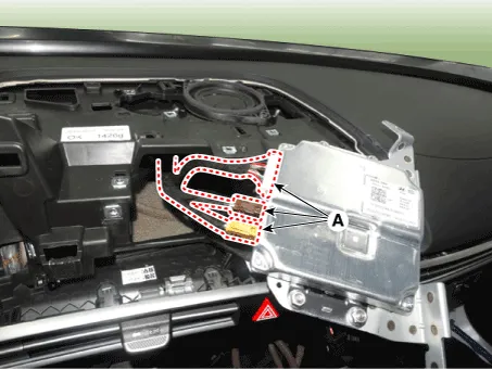
| 4. | Disconnect the ADAS_PRK Unit connectors (A).
|
| Installation |
| 1. | Install in the reverse order of removal. |
| 2. | Connect the cable of Diagnostic tool to the data link connector in driver side crash pad lower panel, and turn on the Diagnostic tool. |
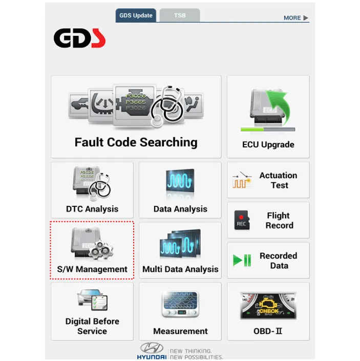
| 3. | Select the 'S/W Management' and 'Car model'.
|
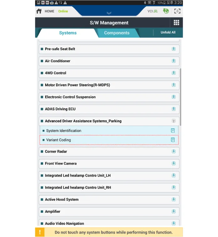
| 4. | Select the 'Advanced Driver Assistance Systems_Parking' and Variant Coding.
|
TroubleshootingDiagnosis with Diagnostic tool1.In the body electrical system, failure can be quickly diagnosed by using the vehicle diagnostic system (Diagnostic tool).
Components and components location Components and Components Location Schematic diagrams Schematic DiagramsParking Collision-Avoidance Assist (PCA) Ultrasonic sensorParking Collision-Avoidance Assist (PCA) Rear view camera Repair procedures RemovalParking Collision-Avoidance Assist (PCA) Unit1.
Other information:
Hyundai Elantra (CN7) 2021-2025 Service Manual: Description and operation
DescriptionThe immobilizer system will disable the vehicle unless the proper ignition key is used, in addition to the currently available anti-theft systems such as car alarms, the immobilizer system aims to drastically reduce the rate of auto theft.1.
Hyundai Elantra (CN7) 2021-2025 Service Manual: Heater Unit
Components and components location Component Location1. Heater unit assemblyCompoents1. Heater unit assembly2. Heater tube cover3. Heater core assembly4. Mode control actuator [LH]5. Dummy PTC6. Temperature control actuator [LH]7. Heater case [LH]8.
Categories
- Manuals Home
- Hyundai Elantra Owners Manual
- Hyundai Elantra Service Manual
- Engine Control / Fuel System
- Driver assistance system
- Engine Electrical System
- New on site
- Most important about car
