Hyundai Elantra: Seat Electrical / Air Ventilation Seat
Hyundai Elantra (CN7) 2021-2025 Service Manual / Body Electrical System / Seat Electrical / Air Ventilation Seat
Components and components location
| Component Location |
[Front Ventilation Seat]
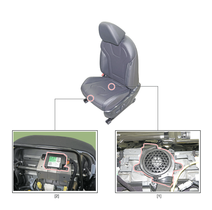
| 1. Ventilation seat blower | 2.Ventilation seat unit |
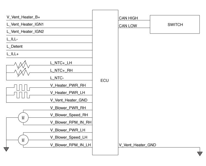
Schematic diagrams
| Circuit Diagram |
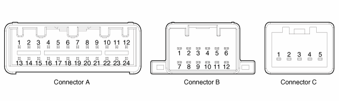
Connector Pin Information
|
Pin no
|
Connector A
|
Connector B
|
Connector C
|
| 1 | Ventilation seat unit IGN 1 | Ventilation heater power | blower ground |
| 2 | Driver blower power | Driver heater power | - |
| 3 | Driver blower spped | Passenger heater power | blower VSP |
| 4 | Driver RPM input | - | blower F/B |
| 5 | Illumination (+) | Driver heater ground | blower VCC |
| 6 | - | Driver ventilation heater ground | |
| 7 | CAN Low | Driver ventilation power | |
| 8 | CAN High | - | |
| 9 | - | - | |
| 10 | LIN | - | |
| 11 | - | Passenger heater ground | |
| 12 | Driver blower ground | Ventilation heater ground | |
| 13 | Ventilation seat unit IGN 1 | ||
| 14 | Passenger blower power | ||
| 15 | Passenger blower speed | ||
| 16 | Passenger blower RPM input | ||
| 17 | Illumination (-) | ||
| 18 | Detent | ||
| 19 | - | ||
| 20 | Driver NTC (+) | ||
| 21 | Passenger NTC (+) | ||
| 22 | Passenger NTC (-) | ||
| 23 | Driver NTC (-) | ||
| 24 | Passenger blower ground |
Repair procedures
| Removal |
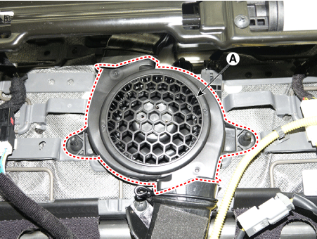
[Ventilation Blower]
| 1. | Disconnect the negative (-) battery terminal. |
| 2. | Remove the front seat. (Refer to Body - "Front Seat Assembly") |
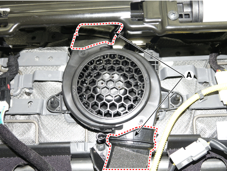
| 3. | Remove the blower duct (A).
|
| 4. | Remove the blower FAN (A) after removing the screws.
|
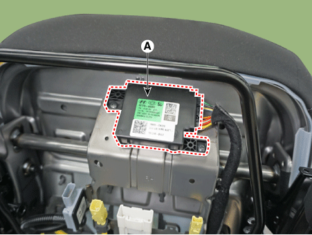
[Ventilation Seat Unit]
| 1. | Disconnect the negative (-) battery terminal. |
| 2. | Remove the front seat. (Refer to Body - "Front seat Assembly") |
| 3. | Loosening the screws and then remove the ventilation seat unit (A) after disconnect the connectors.
|
| Installation |
[Ventilation Blower]
| 1. | Install the blower fan. |
| 2. | Install the duct. |
| 3. | Install the front seat assembly. |
| 4. | Connect the negative (-) battery terminal. |
[Ventilation Seat Unit]
| 1. | Install the ventilation seat unit. |
| 2. | Install the front seat assembly. |
| 3. | Connect the negative (-) battery terminal. |
| Inspection |
Ventilating seat consists of three units : the ventilating seat unit for control, switch for input and and blower for output.
Diagnosis Mode
| 1. | You can enter the diagnosis mode by turning the heater seat button on. |
| 2. | You can enter the diagnosis mode by referring to following description. |
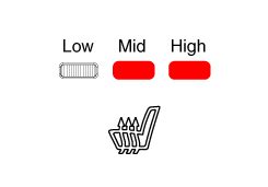
| 3. | Press the heating wire switch as shown below.
|
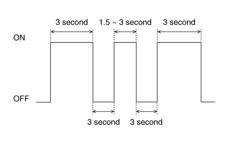
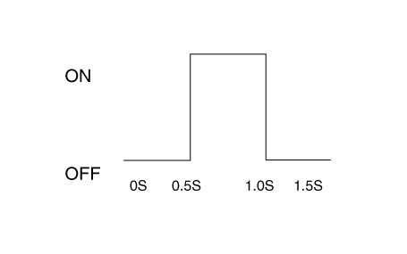
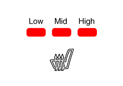
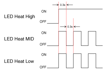
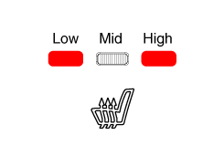
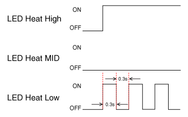
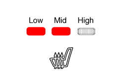
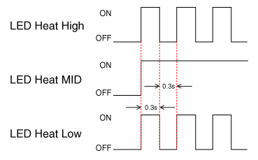
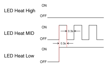
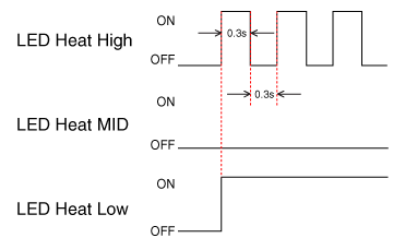
| 4. | When the vehicle enters the diagnostic mode, the three LEDs (Low, Mid, High) in the heating wire section blinks once for 0.5 seconds.
|
| 5. | After entering the diagnostic mode, check the LED status to identify the error.
|
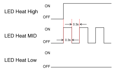
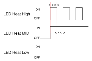
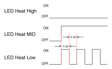
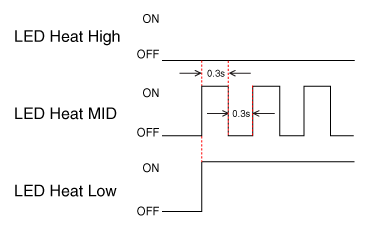
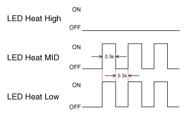
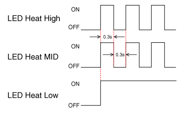
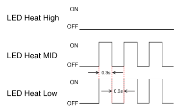
| 6. | You can check the malfunctioning by checking the blinking LED. |
| 7. | The failure data is recorded to the memory by the ventilation seat unit. |
| 8. | Press the heating wire seat switch on the passenger side for 5 seconds or more to make the LED blink four times and delete the failure data in the memory. |
| 9. | Pressing the IGN OFF button will end the diagnosis mode for the heater seat. |
| 10. | You can check whether the heating seat system works properly after turning the IGN ON. If you want to check the error code, you can refer to the procedure of 2 above. |

 Lumber Support Units
Repair procedures
Removal1.Disconnect the negative (-) battery terminal.2.Remove the front seat assembly.(Refer to Body - "Front Seat Assembly")3.Remove the seat back...
Other information:
Hyundai Elantra (CN7) 2021-2025 Service Manual: Memory power seat switch
Components and components location Components Repair procedures Removal1.Disconnect the negative (-) battery terminal.2.Remove the driver door trim.(Refer to Body - "Front Door Trim")3.Remove the memory power switch (A) after disengaging the mounting clips...
Hyundai Elantra (CN7) 2021-2025 Service Manual: Repair procedures
InspectionCheck it by the procedure below to see if the function of the ECM is normal.1.Turn the ignition key to the "ON" position.2.Cover the forward facing sensor.3.Head a light to the rearward looking sensor.4.The ECM should be darkened as soon as the rearward looking sensor detects the light...
Categories
- Manuals Home
- 7th Gen Hyundai Elantra Owners Manual
- 7nd Gen Hyundai Elantra Service Manual
- Drive Mode
- Forward Collision–Avoidance Assist (FCA) (sensor fusion)
- Dimensions, Engine specification, Bulb Wattage
- Engine Compartment
- Specifications
Tire Rotation
To equalize tread wear, HYUNDAI recommends that the tires be rotated according to the maintenance schedule or sooner if irregular wear develops.
During rotation, check the tires for correct balance.
When rotating tires, check for uneven wear and damage. Abnormal wear is usually caused by incorrect tire pressure, improper wheel alignment, out-ofbalance wheels, severe braking or severe cornering. Look for bumps or bulges in the tread or side of the tire. Replace the tire if you find any of these conditions. Replace the tire if fabric or cord is visible. After rotation, be sure to bring the front and rear tire pressures to specification and check lug nut tightness (proper torque is 79~94 lbf·ft [11~13 kgf·m]).

Copyright © 2025 www.helantra7.com