Hyundai Elantra: AVN System / AVN(Audio Video Navigation) head unit
Hyundai Elantra (CN7) 2021-2025 Service Manual / Body Electrical System / AVN System / AVN(Audio Video Navigation) head unit
Components and components location
| Components |
Middle East
Connector Pin Information
|
No
|
Connector A (Int AMP)
|
Connector A (Ext AMP)
|
Connector B
|
| 1 | Rear left speaker (+) | - | - |
| 2 | Reart left speaker (-) | - | MIC Signal (+) |
| 3 | - | AMP Navi Voice (+) | - |
| 4 | - | AMP SPDIF (HI) | - |
| 5 | - | - | Antenna Powr |
| 6 | Camera Power | Camera Power | ILL (+) |
| 7 | Camera Video | Camera Video | MM CAN (HI) |
| 8 | - | - | - |
| 9 | - | - | - |
| 10 | - | - | B+ |
| 11 | - | - | B+ |
| 12 | Steering wheel remote | Steering wheel remote | GND |
| 13 | Front lift speaker (+) | - | GND |
| 14 | Front lift speaker (-) | - | MIC GND |
| 15 | Front right speaker (-) | - | MIC Signal (-) |
| 16 | Front right speaker (+) | - | - |
| 17 | - | AMP Navi Voice (-) | - |
| 18 | - | AMP SPDIF (LOW) | - |
| 19 | - | AMP SPDIF GND | - |
| 20 | Camera Power GND | Camera Power GND | MM CAN (LOW) |
| 21 | Camera Video GND | Camera Video GND | - |
| 22 | - | - | ACC |
| 23 | - | - | - |
| 24 | - | - | - |
| 25 | - | - | - |
| 26 | Steering wheel remote GND | Steering wheel remote GND | - |
| 27 | Rear right speaker (-) | - | - |
| 28 | Rear right speaker (+) | - | - |
| 29 | - | - | - |
| 30 | - | - | - |
| 31 | - | - | - |
| 32 | - | - | - |
| 33 | Camera shield ground | - | IGN 1 |
| 34 | - | - | - |
| 35 | - | - | - |
| 36 | - | - | |
| 37 | - | - | |
| 38 | Speed | Speed |
General
Connector Pin Information
|
No
|
Connector A (Ext AMP)
|
Connector B
|
Connector C
|
| 1 | - | - | - |
| 2 | - | MIC Signal (+) | I-CAN (HI) |
| 3 | AMP Navi Voice (+) | - | - |
| 4 | AMP SPDIF (HI) | - | - |
| 5 | - | - | - |
| 6 | Camera Power | ILL (+) | - |
| 7 | Camera Video | MM CAN (HI) | - |
| 8 | - | - | - |
| 9 | - | - | I-CAN (LOW) |
| 10 | - | B+ | - |
| 11 | USB Detect | B+ | - |
| 12 | Steering wheel remote | GND | - |
| 13 | - | GND | - |
| 14 | - | - | - |
| 15 | - | MIC Signal (-) | - |
| 16 | - | - | MTS Key |
| 17 | AMP Navi Voice (-) | - | - |
| 18 | AMP SPDIF (LOW) | - | - |
| 19 | AMP SPDIF GND | ILL (-) | - |
| 20 | Camera Power GND | MM CAN (LOW) | - |
| 21 | Camera Video GND | - | - |
| 22 | - | ACC | |
| 23 | - | - | |
| 24 | - | Front monitor power | |
| 25 | - | - | |
| 26 | Steering wheel remote GND | - | |
| 27 | - | - | |
| 28 | - | - | |
| 29 | - | - | |
| 30 | - | - | |
| 31 | - | - | |
| 32 | - | - | |
| 33 | Camera shield ground | IGN 1 | |
| 34 | - | - | |
| 35 | - | Front monitor power ground | |
| 36 | - | ||
| 37 | - | ||
| 38 | Speed |
Repair procedures
| Removal |
|

| 1. | Disconnect the negative (-) battery terminal. |
| 2. | When removing with a flat-tip screwdriver or remover, remove the steering column shroud upper panel (A).
|
| 3. | When removing with a flat-tip screwdriver or remover, remove the floor console side garnish (A).
|
| 4. | When removing with a flat-tip screwdriver or remover, remove the crash pad garnish[CTR] (A).
|
| 5. | Remove the heater & A/C control unit. (Refer to Heating, Ventilation and Air Conditioning - "Heater & A/C Control Unit (DATC)") (Refer to Heating, Ventilation and Air Conditioning - "Heater & A/C Control Unit (Manual)") |
| 6. | Remove the AVN head unit (A) after loosening mounting screws.
|
| 7. | Remove the AVN head unit connectors and cables (A).
|
| Installation |
| 1. | Install the AVN head unit. |
| 2. | Install the heater & A/C control unit. |
| 3. | Install the crash pad garnish[CTR]. |
| 4. | Install the floor console side garnish. |
| 5. | Install the steering column shroud upper panel. |
| 6. | Disconnect the negative (-) battery terminal.
|

 Components and components location
Component Location1. AVN head unit2. Crash pad antenna3. Bluelink keyboard & Hands-free mic (Built-in overhead console)4. Steering wheel remote control5...
 External AMP
Components and components location
Components
NO
Connector A
NO
Connector B
1BATT (+)1Subwoofer 2 (+)2BATT (+)2Subwoofer 1 (+)3BATT (+)3Sub woofer speaker (+)4BATT (+)4-5-5-6Multimedia CAN (High)6-7Multimedia CAN (Low)7Navigation voice (+)8ACC8-9-9-10-10-11-11-12-12Rear door speaker - RH (..
Other information:
Hyundai Elantra (CN7) 2021-2025 Owner's Manual: Temperature control
The temperature will increase by turning the knob to the right. The temperature will decrease by turning the knob to the left. The temperature will increase or decrease by 1°F (0.5°C) for each incremental location. When set to the lowest temperature setting, the air conditioning will operate continuously. Adjusting the driver and passenger side temperature equally Press the “SYNC”..
Hyundai Elantra (CN7) 2021-2025 Owner's Manual: Vehicle load limit
Two labels on your driver's door sill show how much weight your vehicle was designed to carry: the Tire and Loading Information Label and the Certification Label. Before loading your vehicle, familiarize yourself with the following terms for determining your vehicle’s weight ratings, from the vehicle's specifications and the Certification Label: Base Curb Weight This is the weight of the..
Categories
- Manuals Home
- 7th Gen Hyundai Elantra Owners Manual
- 7nd Gen Hyundai Elantra Service Manual
- Dimensions, Engine specification, Bulb Wattage
- Fuel gauge
- System disabled
- Forward Collision–Avoidance Assist (FCA) (sensor fusion)
- Integrated Thermal Management Module (ITM)
Air bag collision sensors
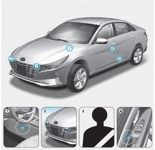
1. SRS control module/Rollover sensor
2. Front impact sensors
3. Side impact sensors (acceleration)
4. Side impact sensors (pressure)

Copyright © 2025 www.helantra7.com