Hyundai Elantra (CN7): Evaporative Emission Control System / Canister
Repair procedures
| Removal |
| 1. | Turn the ignition switch OFF and disconnect the negative (-) battery cable. |
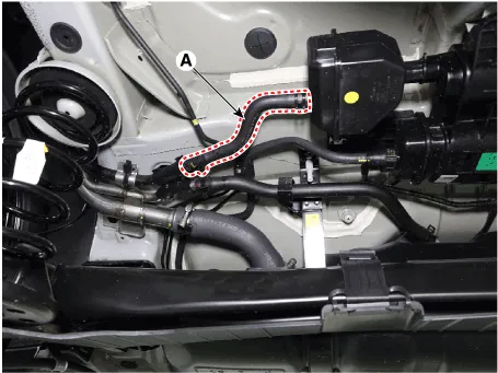
| 2. | Disconnect the vent hose (A).
|
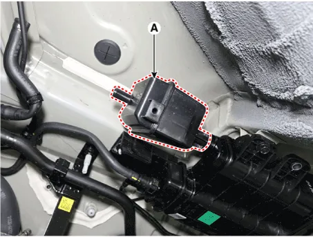
| 3. | Remove the fuel tank air filter (A) by rotating it 30 degrees.
|

| 4. | Disconnect the vapor hose quick-connectors (A).
|

| 5. | Remove the canister (A).
|

| Inspection |
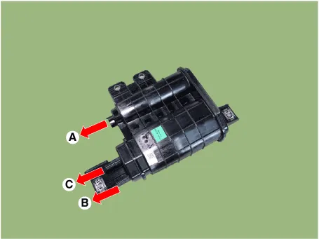
| 1. | Check for the following items visually.
A : Canister ↔ Atmosphere B : Canister ↔ Fuel Tank C : Canister ↔ Intake Manifold |
| Installation |
| 1. | Install in the reverse order of removal. |
Schematic Diagram1. Air cleaner2. Delivery pipe & injector3. Engine4. Purge control solenoid valve (PCSV)5. Fuel tank air filter6. Fuel pump7. Fuel filler neck8.
Description and operation DescriptionA ratchet tightening device on the threaded fuel filler cap reduces the chances of incorrect installation, which would seal the fuel filler.
Other information:
Hyundai Elantra (CN7) 2021-2025 Service Manual: Blower Motor
Repair procedures Inspection1.Connect the battery voltage and check the blower motor rotation.Replacement1.Disconnect the negative (-) battery terminal.2.Disconnect the blower motor connector (A) and then remove the blower motor (B) after loosening the screws.
Hyundai Elantra (CN7) 2021-2025 Service Manual: Front View Camera Unit
Schematic diagrams Circuit Diagram Repair procedures Removal1.Disconnect the negative (-) battery terminal.2.Remove the cover (A) & (B).3.Disconnect the front view camera unit connector (A).4.Separate the fixed points (A) of coupler.5.
Categories
- Manuals Home
- Hyundai Elantra Owners Manual
- Hyundai Elantra Service Manual
- Front Bumper
- Towing
- Vehicle Information
- New on site
- Most important about car
