Hyundai Elantra (CN7): Audio / Audio Unit
Components and components location
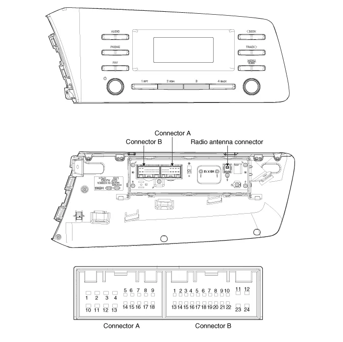
| Components |
|
No
|
Connector A
|
Connector B
|
| 1 | Rear left speaker (+) | MM_CAN High |
| 2 | Front left speaker (+) | - |
| 3 | Front right speaker (+) | - |
| 4 | Rear right speaker (+) | Steering wheel remote |
| 5 | - | - |
| 6 | Door open | USB DATA (+) |
| 7 | IGN1 | USB VOC |
| 8 | Illumination (+) | - |
| 9 | Detent | - |
| 10 | Rear left speaker (-) | Mic (+) |
| 11 | Front left speaker (-) | ACC |
| 12 | Front right speaker (-) | B+ |
| 13 | Rear right speaker (-) | MM_CAN Low |
| 14 | - | - |
| 15 | - | - |
| 16 | - | Vehicle Speed |
| 17 | Illumination (-) | Steering wheel remote GND |
| 18 | - | USB DATA (-) |
| 19 | USB GND | |
| 20 | - | |
| 21 | - | |
| 22 | Mic (-) | |
| 23 | - | |
| 24 | GND |
|
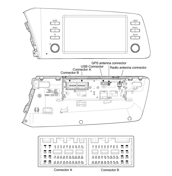
No
|
Connector A (Int AMP)
|
Connector A (Ext AMP)
|
Connector B
|
| 1 | Rear left speaker (+) | - | - |
| 2 | Reart left speaker (-) | - | MIC Signal (+) |
| 3 | - | AMP Navi Voice (+) | - |
| 4 | - | AMP SPDIF (HI) | - |
| 5 | - | - | Antenna Powr |
| 6 | Camera Power | Camera Power | ILL (+) |
| 7 | Camera Video | Camera Video | MM CAN (HI) |
| 8 | - | - | - |
| 9 | - | - | - |
| 10 | - | - | B+ |
| 11 | - | - | B+ |
| 12 | Steering wheel remote | Steering wheel remote | GND |
| 13 | Front lift speaker (+) | - | GND |
| 14 | Front lift speaker (-) | - | MIC GND |
| 15 | Front right speaker (-) | - | MIC Signal (-) |
| 16 | Front right speaker (+) | - | - |
| 17 | - | AMP Navi Voice (-) | - |
| 18 | - | AMP SPDIF (LOW) | - |
| 19 | - | AMP SPDIF GND | - |
| 20 | Camera Power GND | Camera Power GND | MM CAN (LOW) |
| 21 | Camera Video GND | Camera Video GND | - |
| 22 | - | - | ACC |
| 23 | - | - | - |
| 24 | - | - | - |
| 25 | - | - | - |
| 26 | Steering wheel remote GND | Steering wheel remote GND | - |
| 27 | Rear right speaker (-) | - | - |
| 28 | Rear right speaker (+) | - | - |
| 29 | - | - | - |
| 30 | - | - | - |
| 31 | - | - | - |
| 32 | - | - | - |
| 33 | - | - | IGN 1 |
| 34 | - | - | - |
| 35 | - | - | - |
| 36 | - | - | |
| 37 | - | - | |
| 38 | Speed | Speed |
Repair procedures
| Removal |
|

| 1. | Disconnect the negative (-) battery terminal. |
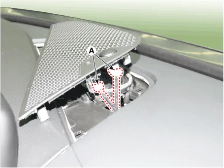
| 2. | Using a flat-tip screwdriver or remover, remove the photo sensor cover (A).
|
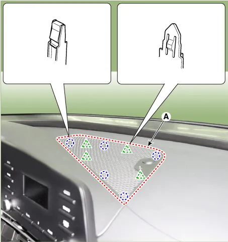
| 3. | Disconnect photo sensor connector and security sensor connector (A).
|
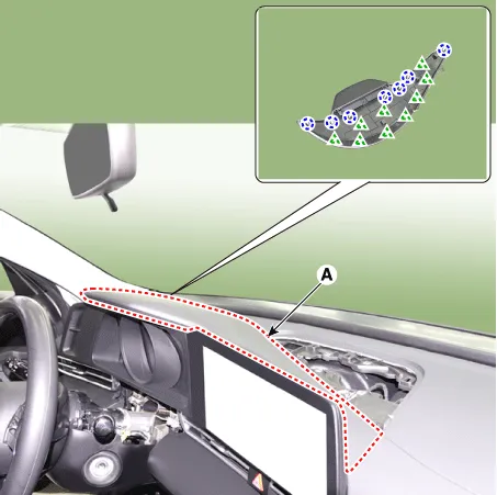
| 4. | Using a flat-tip screwdriver or remover, remove the cluster fascia upper garnish (A).
|
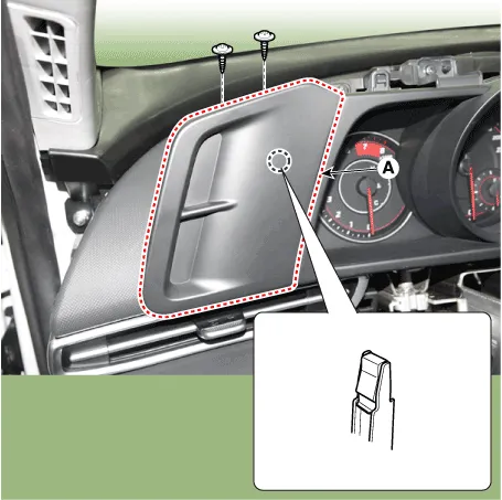
| 5. | Remove the cluster fascia side panel (A) after mounting screws.
|
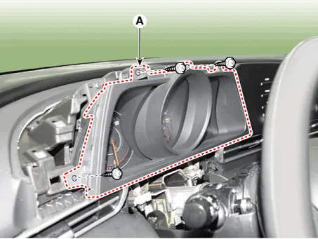
| 6. | Remove the cluster fascia panel (A) after loosening mounting screws.
|
| 7. | Remove the audio head unit (A) after loosening the screws.
|
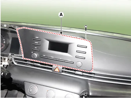
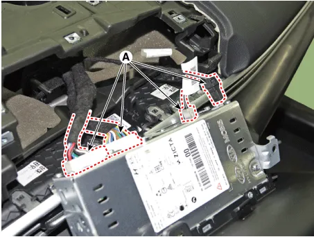
| 8. | Remove the audio head unit after disconnecting the connectors and cable (A).
|
| Installation |
| 1. | Connect the audio unit connectors and cable. |
| 2. | Install the audio head unit. |
| 3. | Install the cluster fascia panal. |
| 4. | Install the cluster fascia side panal. |
| 5. | Install the cluster fascia upper garnish. |
| 6. | Install the photo sensor cover. |
| 7. | Connect the negative (-) battery terminal.
|
SpecificationsAudio Items AUDIO ModelRADIO/MP3Power supplyDC 14.4VParasitic currentMax 21W X 4Antenna80PF 75ΩTuning typePLL SYNTHESIZED TUNING
Repair procedures Inspection1.Troubleshooting for Speaker(1)Basic inspection of speakerInspect the sound from speaker after verifying that the speaker mounting screws is removed and the wiring connector is connected precisely to remove vibration transmitted from body trims and surrounding parts.
Other information:
Hyundai Elantra (CN7) 2021-2026 Service Manual: Head Lamp Leveling Device
Components and components location Component Location1. Head lamp leveling actuator2. Head lamp leveling switch Head Lamp Leveling Switch Schematic diagrams Schematic Diagrams Repair procedures Replacement1.Disconnect the negative (-) battery terminal.
Hyundai Elantra (CN7) 2021-2026 Service Manual: Rear View Monitor (RVM)
Description and operation DescriptionRear view camera will activate when the backup light is ON with the ignition switch ON and the shift lever in the R position.This system is a supplemental system that shows behind the vehicle through the AV monitor or the ECM (Reverse Display Room Mirror) mirror while backing-up.
Categories
- Manuals Home
- Hyundai Elantra Owners Manual
- Hyundai Elantra Service Manual
- Drive Mode
- Instrument Panel Overview
- Front Radar Unit
- New on site
- Most important about car
