Hyundai Elantra (CN7): Brake System / Brake bleeding procedures
| Brake System Bleeding |
|

| 1. | Make sure the brake fluid in the reservoir is at the MAX (upper) level line. |
| 2. | Have someone slowly pump the brake pedal several times, and then apply pressure. |
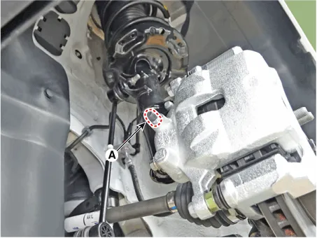
| 3. | Loosen the right-rear brake bleed screw (A) to allow air to escape from the system. Then tighten the bleed screw securely. [Front]
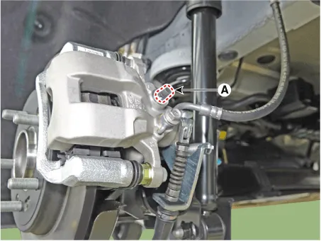
[Rear torsion beam parking cable type]
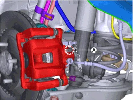
[Rear torsion beam EPB type]
[Rear multi link parking cable type]
[Rear multi link EPB type]
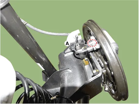
[Rear drum brake type]
|


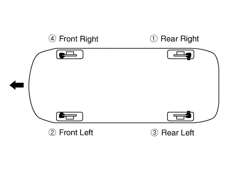
| 4. | Repeat the procedure for wheel in the sequence shown below until air bubbles no longer appear in the fluid. |
| 5. | Follow the sequence as shown below.
|
| 6. | Refill the master cylinder reservoir to MAX (upper) level line. |
| 1. | Remove the reservoir cap and fill the brake reservoir with brake fluid.
|
| 2. | Connect a clear plastic tube to the wheel cylinder bleeder plug and insert the other end of the tube into a half filled clear plastic bottle. |
| 3. | Connect the diagnostic tool to the data link connector located underneath the dash panel. |
| 4. | Select and operate according to the instructions on the diagnostic tool screen.
|

| 5. | Have someone slowly pump the brake pedal several times, and then apply pressure. |
| 6. | Pump the brake pedal several times, and then loosen the bleeder screw until fluid starts to run out without bubbles. Then close the bleeder screw (A). [Front]
[Rear torsion beam parking cable type]
[Rear torsion beam EPB type]
[Rear multi link parking cable type]
[Rear multi link EPB type]
[Rear drum brake type]
|
| 7. | Repeat the procedure for wheel in the sequence shown below until air bubbles no longer appear in the fluid. |
| 8. | Follow the sequence as shown below.
|
| 9. | Refill the master cylinder reservoir to MAX (upper) level line. |
Special Service Tools Tool (Number and Name) Illustration Use 09581-11000Piston expanderSpreading the front disc brake piston.
Other information:
Hyundai Elantra (CN7) 2021-2026 Service Manual: Rear Combination Lamp
Repair procedures RemovalOutside Combination Lamp1.Disconnect the negative (-) battery terminal.2.Remove the combination lamp cover (A).3.Disconnect the rear combination lamp connector (A).4.Loosen the mounting nuts and remove the rear conbination lamp (A).
Hyundai Elantra (CN7) 2021-2026 Service Manual: Parking Collision-Avoidance Assist (PCA)
Components and components location Components and Components Location Schematic diagrams Schematic DiagramsParking Collision-Avoidance Assist (PCA) Ultrasonic sensorParking Collision-Avoidance Assist (PCA) Rear view camera Repair procedures RemovalParking Collision-Avoidance Assist (PCA) Unit1.
Categories
- Manuals Home
- Hyundai Elantra Owners Manual
- Hyundai Elantra Service Manual
- Auto Hold. Warning messages
- Front Bumper
- Troubleshooting
- New on site
- Most important about car
