Hyundai Elantra (CN7): Lighting System / Rear Combination Lamp
Repair procedures
| Removal |
| 1. | Disconnect the negative (-) battery terminal. |
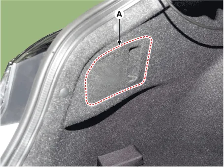
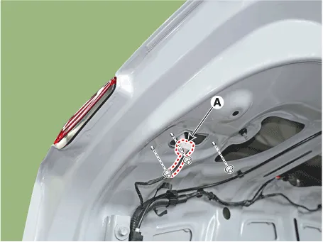
| 2. | Remove the combination lamp cover (A).
|
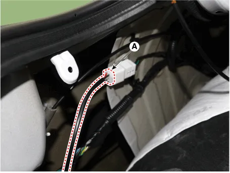
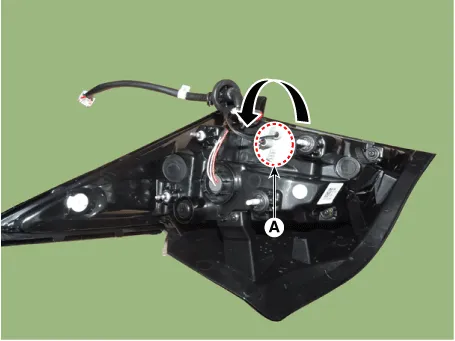
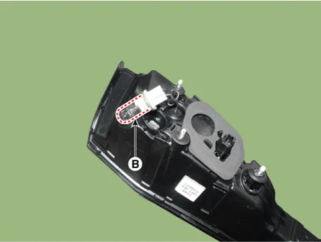
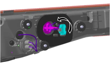
| 3. | Disconnect the rear combination lamp connector (A).
|
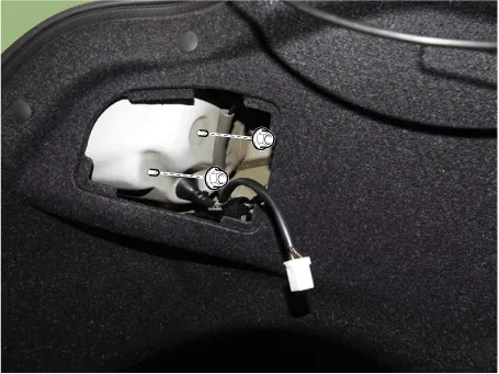
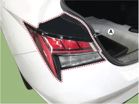
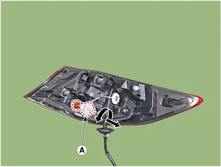
| 4. | Loosen the mounting nuts and remove the rear conbination lamp (A).
|
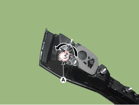
| 5. | Remove the socket (A) and replace the bulb (B).
|
| 1. | Disconnect the negative (-) battery terminal. |
| 2. | Remove the trunk lid trim. (Refer to Body - "Trunk Lid Trim") |
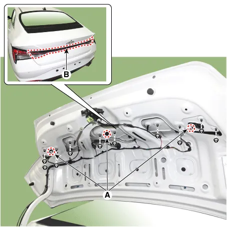
| 3. | Disconnect the rear inside combination lamp connectors and trunk lid button connector (A). |
| 4. | Loosen the mounting nuts and remove the rear inside combination lamp (B).
|
| 5. | Remove the rear inside combination lamp sockec [back-up lamp] (A) and replace the bulb (B).
|
| 6. | Remove the rear inside combination lamp sockec [tail lamp] (A) and replace the bulb (B).
|
| Replacement |
| 1. | Turn the head lamp power off. |
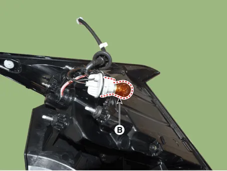
| 2. | Remove the bulb socket and turn signal lamp bulb (A) from the lamp assembly.
|
| 1. | Turn the head lamp power off. |
| 2. | Remove the trunk lid trim. (Refer to Body - "Trunk Lid Trim") |
| 3. | Remove the bulb socket and turn signal lamp bulb (A) from the lamp assembly.
|
| Installation |
| 1. | Connecting the lamp connector. |
| 2. | Install the inside/outside rear combination lamp assembly. |
| 3. | Install the trunk lid trim. [Inside combination lamp only] |
Repair procedures Removal1.Disconnect the negative (-) battery terminal.2.Remove the rear package tray trim.(Refer to Body - "Rear Package Tray Trim")3.
Repair procedures RemovalMood lamp unit1.Disconnect the negative (-) battery terminal.2.Remove the main crash pad assembly.(Refer to Body - "Main Crash Pad Assembly")3.
Other information:
Hyundai Elantra (CN7) 2021-2026 Service Manual: Repair procedures
Variant Coding When you need variant coding:– Replace Front View Camera with a new one※ EOL Variant Coding and calibration required for new replacementFront View Camera Variant CodingFront view camera variant coding makes it possible to operate functions for each vehicle type.
Hyundai Elantra (CN7) 2021-2026 Service Manual: Description and operation
DescriptionThe cruise control system is engaged by the cruise "ON/OFF" main switch located on right of steering wheel column. The system has the capability to cruise, coast, accelerate and resume speed.It also has a safety interrupt, engaged upon depressing brake or shifting select lever.
Categories
- Manuals Home
- Hyundai Elantra Owners Manual
- Hyundai Elantra Service Manual
- Auto Hold. Warning messages
- Integrated Thermal Management Module (ITM)
- Engine Mechanical System
- New on site
- Most important about car
