Hyundai Elantra (CN7): Fuel Delivery System / Delivery Pipe
Repair procedures
| Removal |
|

| 1. | Release the residual pressure in fuel line. (Refer to Fuel Delivery System - "Release Residual Pressure in Fuel Line") |
| 2. | Turn the ignition switch OFF and disconnect the battery negative (-) cable.
|

| 3. | Remove the intake manifold. (Refer to Engine Mechanical System - "Intake Manifold") |
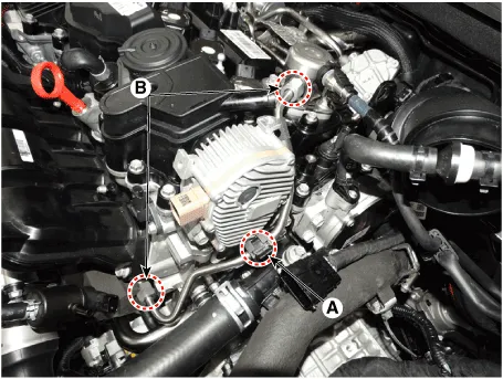
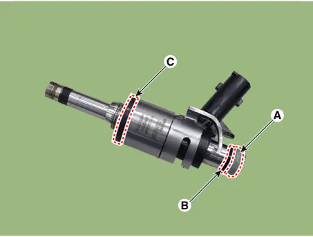
| 4. | Use the special service tool [SST No. : 09314-3Q100 or 09314-27130] to remove the high pressure fuel pipe function block mounting bolt (A) and removing the flange nut (B).
|
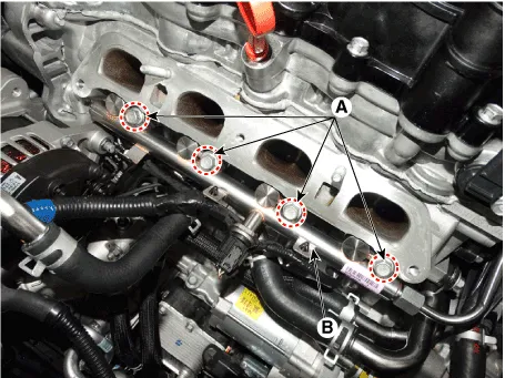
| 5. | Remove the installation bolt (A), and then remove the delivery pipe and injector assembly (B).
|
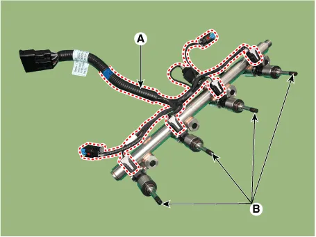
| 6. | Disconnect the injector & rail pressure sensor connector (A). |
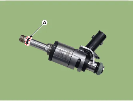
| 7. | Remove the fixing clip (A), and then separate the injector from the delivery pipe
|
| Installation |
| 1. | Install in the reverse order of removal.
|

Repair procedures Removal1.Turn the ignition switch OFF and disconnect the negative (-) battery cable.2.Disconnect the accelerator position sensor connector (A).
Repair procedures Removal • In case of removing the high pressure fuel pump, high pressure fuel pipe, delivery pipe, and injector, there may be injury caused by leakage of the high pressure fuel.
Other information:
Hyundai Elantra (CN7) 2021-2026 Service Manual: Compressor
Description and operation DescriptionThe compressor is the power unit of the A/C system.It is located on the side of engine block and driven by a V-belt of the engine.The compressor changes low pressure and low temperature refrigerant gas into high pressure and high temperature refrigerant gas.
Hyundai Elantra (CN7) 2021-2026 Service Manual: Receiver-Drier
Repair procedures Replacement1.Remove the condenser.2.Remove the cap (A) on the bottom of the condenser with a L wrench. Tightening torque : 9.81 - 14.71 N.m (1.0 - 1.5 kgf.m, 7.2 - 10.8 lb-ft) 3.Remove the receiver-drier (A) from condenser using a long nose plier.
Categories
- Manuals Home
- Hyundai Elantra Owners Manual
- Hyundai Elantra Service Manual
- Drive Mode
- Troubleshooting
- Repair procedures
- New on site
- Most important about car
