
Hyundai Elantra (CN7): Air Conditioning System / Compressor
Description and operation
| Description |
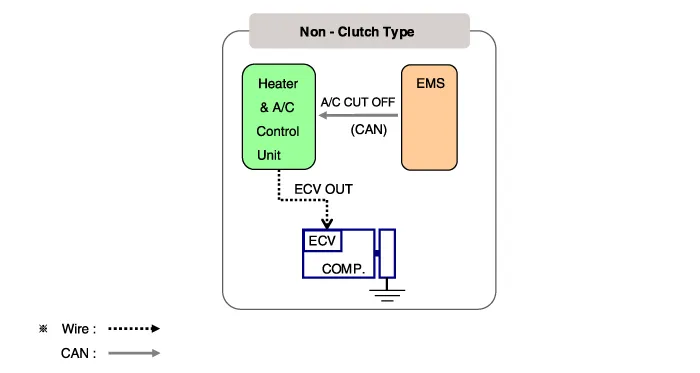
Components and components location
| Components Location |
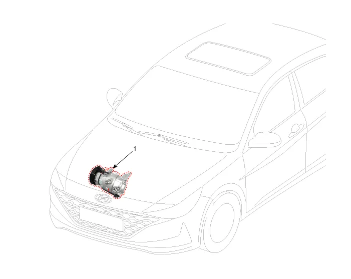
| 1. Compressor |
| Components |
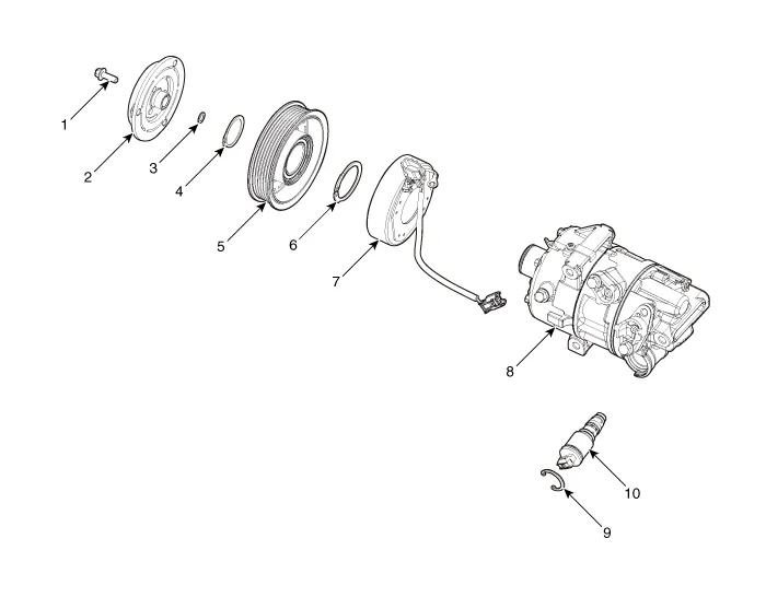
| 1. Clutch bolt 2. Disc & Hub assembly 3. Air gap spacer 4. Retainer (A) 5. Pulley 6. Retainer (B) | 7. Clutch magnetic coil 8. Compressor 9. Electric Control Valve(ECV) Snap ring 10. Electric Control Valve (ECV) |
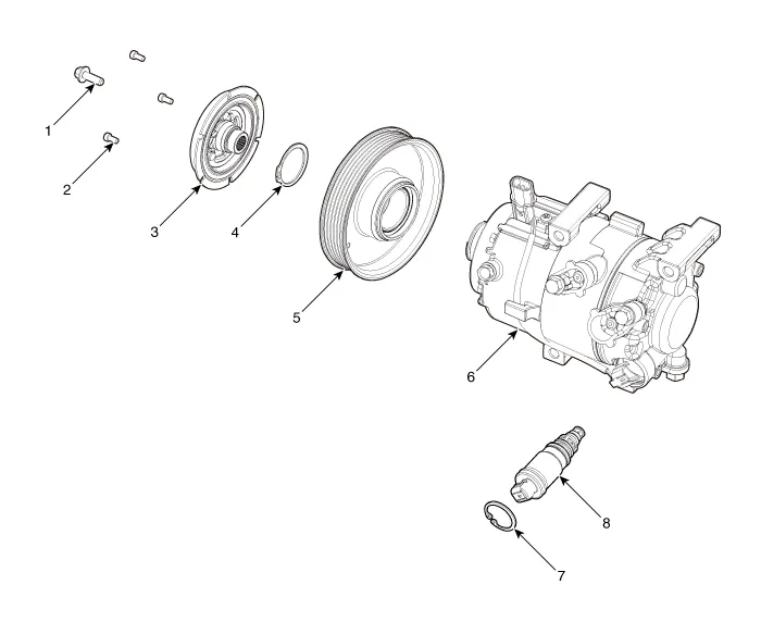
| 1. Clutch bolt 2. Limiter bolt 3. Disc & Hub assembly 4. Snap ring | 5. Pulley 6. Compressor 7. Electric Control Valve(ECV) Snap ring 8. Electric Control Valve (ECV) |
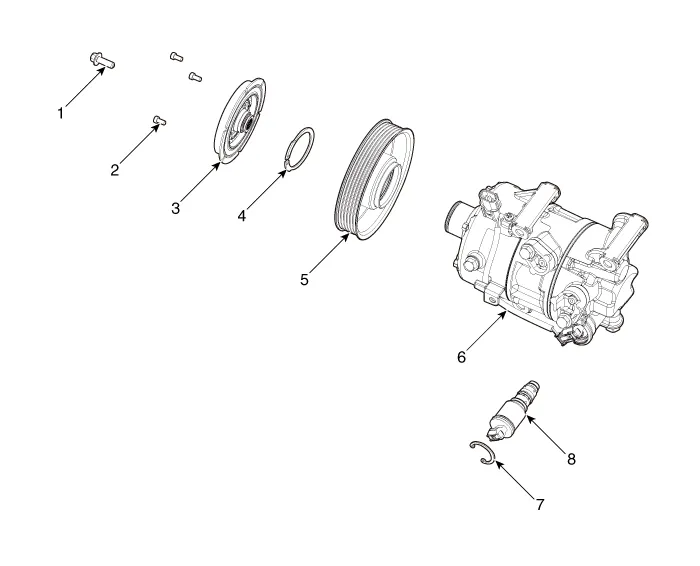
| 1. Clutch bolt 2. Limiter bolt 3. Disc & Hub assembly 4. Snap ring | 5. Pulley 6. Compressor 7. Electric Control Valve(ECV) Snap ring 8. Electric Control Valve (ECV) |
Repair procedures
| Removal |
Precautions for using the plastic pulley
|

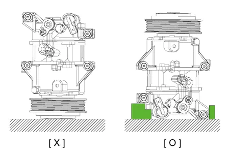
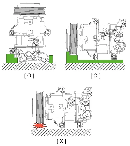
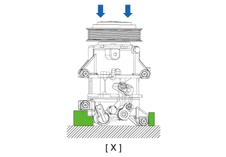
| 1. | If the compressor is marginally operable, run the engine at idle speed, and let the air conditioning work for a few minutes, then shut the engine off. |
| 2. | Disconnect the negative (-) battery terminal. |
| 3. | Recover the refrigerant with a recovery / charging station. |
| 4. | Remove the engine room under cover. (Refer to Engine Mechanical System - "Engine Room Cover") |
| 5. | Remove the front wheel guard. (Refer to Body - "Front Wheel Guard") |
| 6. | Loosen the drive belt. (Refer to Engine Mechanical System - "Drive Belt") |
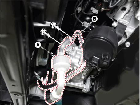
| 7. | Remove the bolts, then disconnect the suction line (A) and discharge line (B) from the compressor.
|
| 8. | Disconnect the compressor switch connector (A).
|

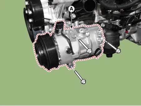
| 9. | Remove the compressor (A) by loosening the mounting bolts.
|
| Installation |
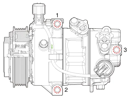
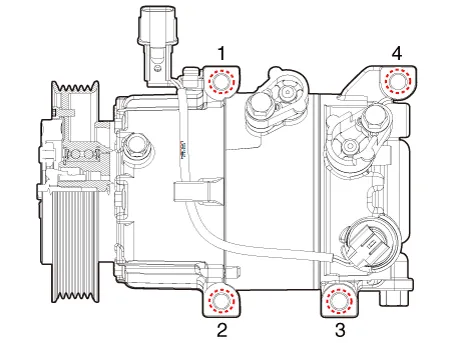
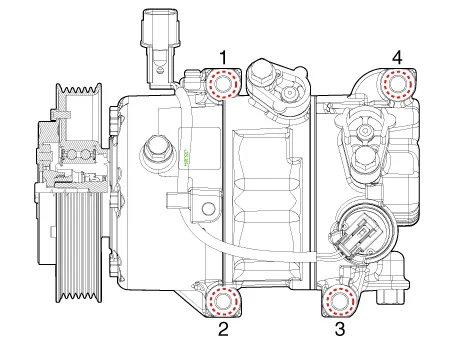
| 1. | Make sure the compressor mounting bolt with the correct length is screwed in. Tighten the mounting bolts with the specified tightening order.
[Gasoline 1.6 MPI]
[Gasoline 1.6 T-GDI, Gasoline 2.0 MPI NU]
[Gamma 1.6 MPI]
|
| 2. | To install, reverse the removal procedure.
|
| Inspection |
| 1. | Check the plated parts of the limiter & hub assembly for color changes, peeling or other damage. If there is damage, replace the assembly. |
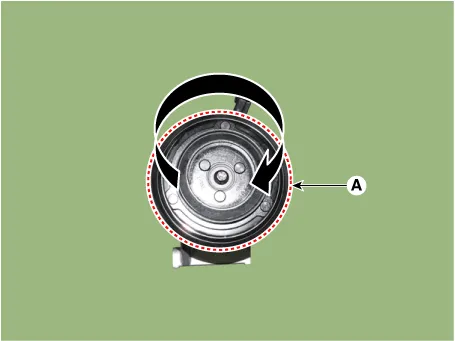
| 2. | Check the pulley (A) bearing play and drag by rotating the pulley by hand. Replace the pulley with a new one if it is noisy or has excessive play / drag.
|
| External Control Valve Compressor Inspection (Diagnostic tool) |
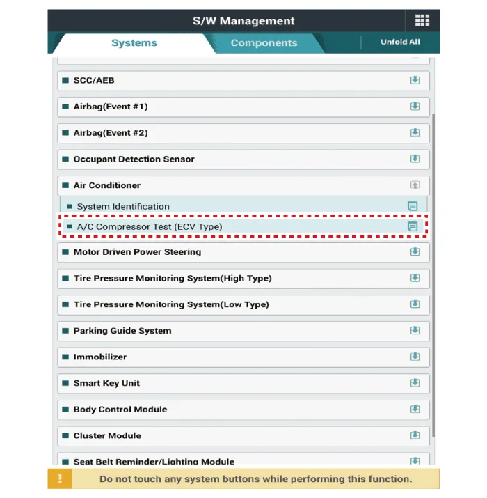
| 1. | Connect diagnostic tool to the vehicle and select 'Aircon Compressor Test(ECV type)' [ECV1]
|
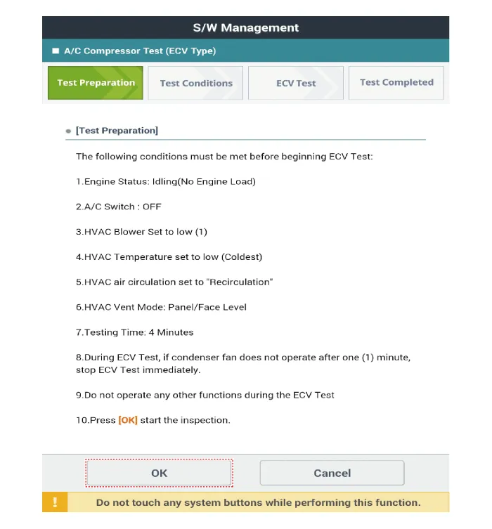
| 2. | Make the vehicle ready as the diagnostic tool instruction on the monitor. (Turn off A/C 'switch' only)
|
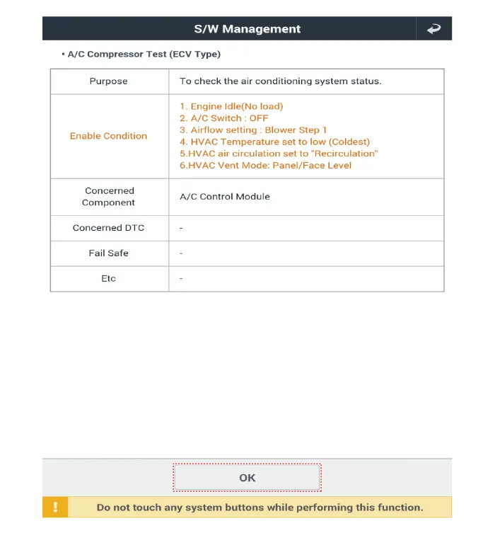
| 3. | Check if other DTC codes are found before inspect ECV compressor. If so, solve that problems first. If not, press 'OK' button to continue.
|

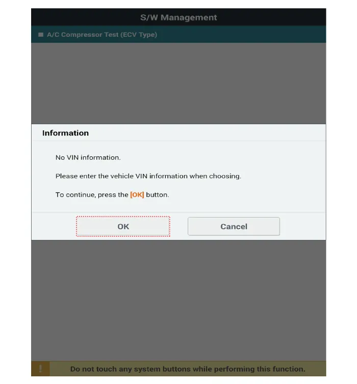
| 4. | Start inspection
|
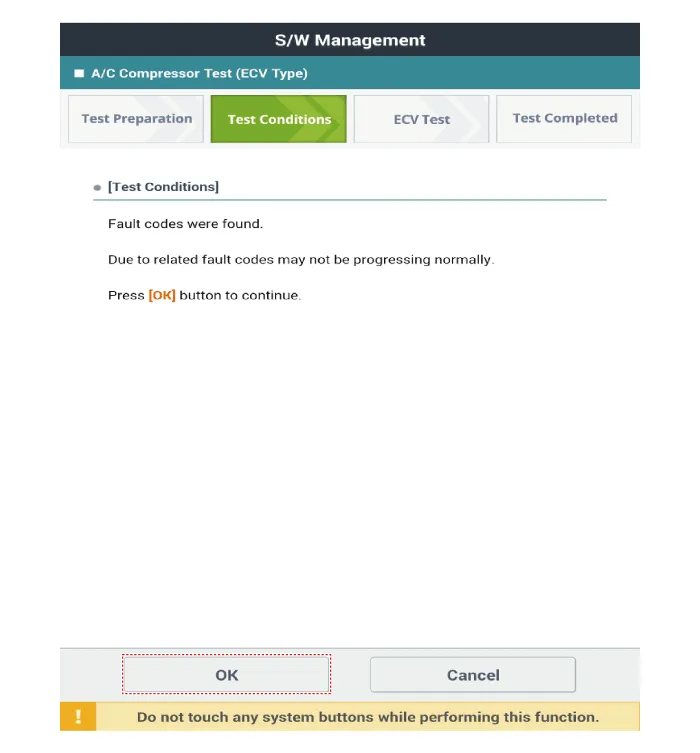

| 5. | Check the result of inspection. [ECV7]
[ECV8]
|
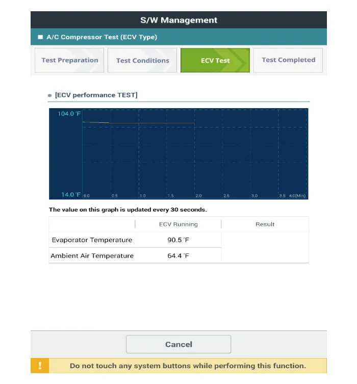
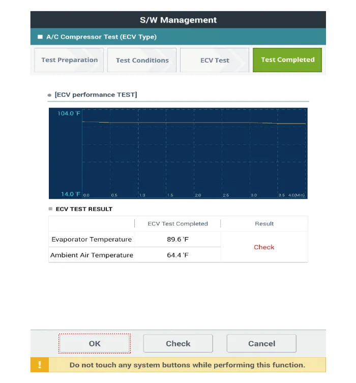
| 6. | If the result shows "Check" , click "Check" and follow the instruction.
|
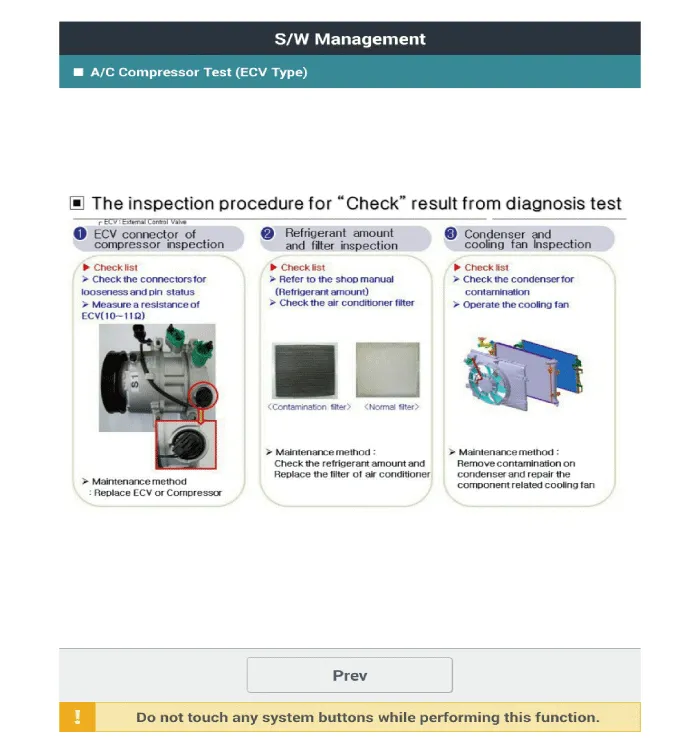
| 7. | Inspect ECV again from the first step. |
| Disassembly |
| 1. | Remove the engine room under cover. (Refer to Engine Mechanical System - "Engine Room Cover") |
| 2. | Remove the front wheel guard. (Refer to Body - "Front Wheel Guard") |
| 3. | Loosen the drive belt. (Refer to Engine Mechanical System - "Drive Belt") |
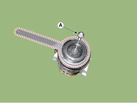
| 4. | Remove the clutch bolt (A) while holding the pulley with a clutch bolt remover (09977-3R000).
|
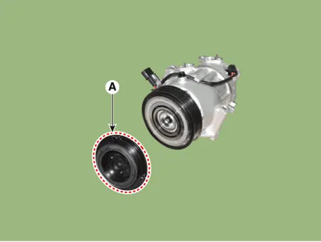
| 5. | Remove the disc & hub assembly (A).
|
| 6. | Remove the snap ring (A) with a snap ring plier.
|
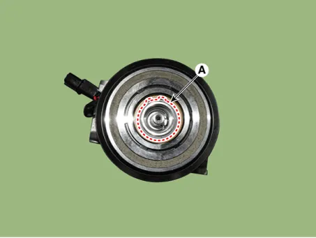
| 7. | Remove the pulley (A).
|
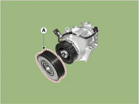
| 8. | Reassemble in the reverse order of disassembly.
|
Components and components location Components Location1. Refrigerant Pipe Assembly Repair procedures Replacement1.If the compressor is marginally operable, run the engine at idle speed, and let the air conditioning work for a few minutes, then shut the engine off.
Components and components location Components Location[General type]1. Condenser[N Line]1. Condenser Repair procedures Inspection1.Check the condenser fins for clogging and damage.
Other information:
Hyundai Elantra (CN7) 2021-2026 Service Manual: A/C Pressure Transducer
Description and operation DescriptionThe A/C Pressure Transducer (APT) converts the pressure value of high pressure line into voltage value after measuring it. By converted voltage value, engine ECU controls the cooling fan by operating it high speed or low speed.
Hyundai Elantra (CN7) 2021-2026 Service Manual: Desctiprion and operation
DescriptionADAS_PRK is a unit that controls the functions required for ADAS parking. If the ADAS_PRK is applied, the parking distance warning function is also controlled by the ADAS_PRK.System FunctionParking Collision-Avoidance Assist (PCA)PCA is a parking safety system that assists in collision warning and emergency braking in the event of a coll
Categories
- Manuals Home
- Hyundai Elantra Owners Manual
- Hyundai Elantra Service Manual
- General Tightening Torque Table. General information
- Specifications
- Engine Mechanical System
- New on site
- Most important about car
