Hyundai Elantra (CN7): Parking Distance Warning (PDW) / Description and operation
Hyundai Elantra (CN7) 2021-2025 Service Manual / Advanced Driver Assistance System (ADAS) / Parking Distance Warning (PDW) / Description and operation
| Description |
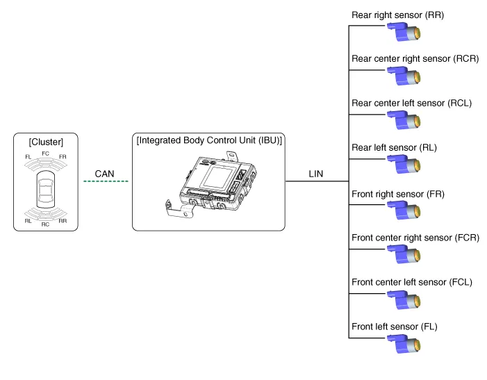
| • | PDW consists of 8 sensors (front : 4 units, rear : 4 units) that are used to detect obstacles and transmit the result in three separate warning levels, the first, second and third to IBU via LIN communication. |
| • | IBU decides the alarm level by the transmitted communication message from the slave sensors, then operates the buzzer or transmits the data for display. |
Block Diagram
System Operation Specification
| Initial mode |
| 1. | System initializing time
|
| 2. | PDW recognizes LID and sets the sensor ID up during initialization. |
| 3. | PDW activates each sensor and then executes the diagnosis after finishing initialization of IPM(IBU). |
| 4. | PDW starting buzzer is normally worked, when sensor does not send an error message and after finishing error diagnosis. |
| 5. | If any failure is received from the any sensors, PDW starting buzzer does not work but the failure alarm is operated for a moment. If you have display option, warning sign is also shown on it.
|

| 6. | IBU memorizes the completed initializing status of sensor. |
| Normal mode |
| 1. | PDW-F : Lin communication starts and keeps the routine after IGN1 ON+D gear + below 10 km/h. PDW-R : Lin communication starts and keeps the routine after IGN1 ON+R gear |
| 2. | After initializing, the routine starts at once without PDW starting warning sound. |
| 3. | Alarms of obstacle consists of 3 level 1,2,3 step and 1,2 alarm sounds intermittently and 3 alarm sounds continuously. 1 level alarm doesn't exist in the front ultrasonic sensor. |
| 4. | In display, the data of each sensor is sent from IBU to display, for example cluster. CAN communication is used for transmission and maximum gateway time is 50ms. |
| 5. | The efficient vehicle speed of PDW operation is under 10Km/h. |
| 6. | Operation doesn't start or stops at gear N, P. |
Sensing Area
| Level | Distance range | Allowed range |
| 1 | Front : 61 - 100 cm (24.02 - 39.37 in.) / Rear : 61 - 120 cm (24.02 - 47.2 in.) | ± 15 cm (5.90 in.) |
| 2 | 31 - 60 cm (12.20 - 23.62 in.) | ± 15 cm (5.90 in.) |
| 3 | 0 - 30 cm (0 - 11.81 in) | ± 10 cm (3.94 in.) |
*Measurement condition : PVC pipe - Diameter 75 mm (0.0394 in.), length 1 m (39.37 in.), at normal temperature
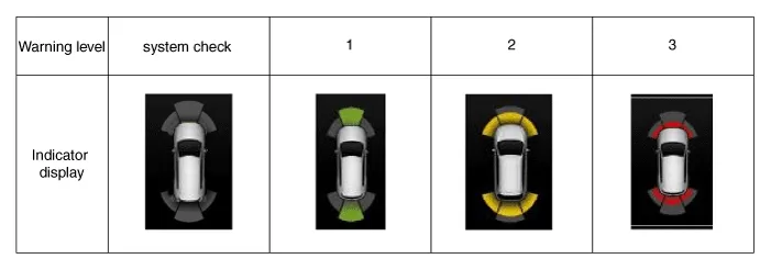
Display Alarm Indicator Specification
Component Location1. Integrated body control unit (IBU) 2. Ultrasonic sensor
Other information:
Hyundai Elantra (CN7) 2021-2025 Service Manual: Photo Sensor
Description and operation Description 1.The photo sensor is located at the center of the defrost nozzles.2.The photo sensor contains a photovoltaic (sensitive to sunlight) diode. The solar radiation received by its light receiving portion, generates an electromotive force in proportion to the amount of radiation received which is transferred to
Hyundai Elantra (CN7) 2021-2025 Service Manual: Repair procedures
Inspection1.Check for resistance between terminals in each switch position (LH).[LH : Audio + Hands free] Switch Resistance (±5%) SEEK Up430 ΩSEEK Down1.11 kΩMODE2.11 kΩMUTE3.11 kΩVolume (+)4.
Categories
- Manuals Home
- Hyundai Elantra Owners Manual
- Hyundai Elantra Service Manual
- Seat Belts
- Driving your vehicle
- Vehicle Identification Number (vin), Vehicle Certification Label
- New on site
- Most important about car
Copyright © 2025 www.helantra7.com - 0.0164