Hyundai Elantra (CN7): Engine And Transaxle Assembly / Engine And Transaxle Assembly
Hyundai Elantra (CN7) 2021-2026 Service Manual / Engine Mechanical System / Engine And Transaxle Assembly / Engine And Transaxle Assembly
Repair procedures
| Removal |
|

|

| 1. | Disconnect the negative battery terminal. |
| 2. | Remove the engine cover. (Refer to Engine and Transaxle Assembly - "Engine Cover") |
| 3. | Remove the engine room under cover. (Refer to Engine and Transaxle Assembly - "Engine Room Under Cover") |
| 4. | Drain the coolant. (Refer to Cooling System - "Coolant") |
| 5. | Recover the A/C refrigerant and then remove the high & low pressure pipes of A/C compressor. (Refer to Heating, Ventilation Air conditioning - "Compressor") |
| 6. | Remove the air duct and air cleaner assembly. (Refer to Intake and Exhaust System - "Air Cleaner") |
| 7. | Remove the battery and battery tray. (Refer to Engine Electrical System - "Battery") |
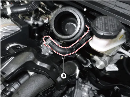
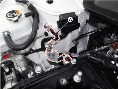
| 8. | Disconnect the brake booster vacuum hose (A).
|
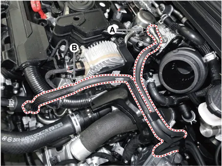
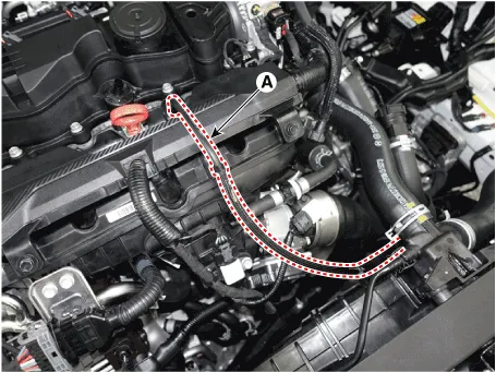
| 9. | Disconnect the fuel hose (A) and PCSV hose (B).
|
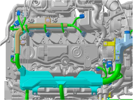
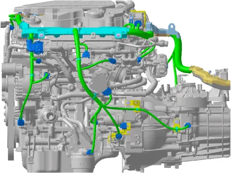
| 10. | Disconnect the wiring connectors and harness clamps and remove the connector brackets around the engine and transaxle assembly.
|
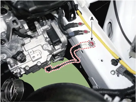
| 11. | Disconnect the engine ground cable (A).
|
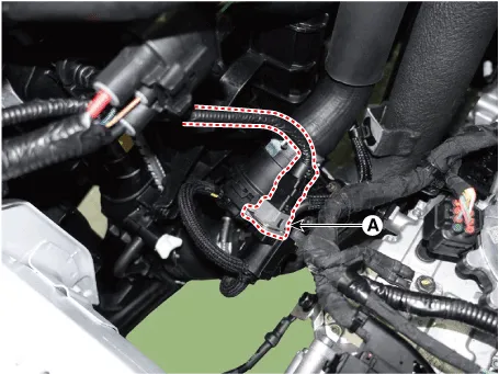
| 12. | Disconnect the transaxle ground cable (A).
|
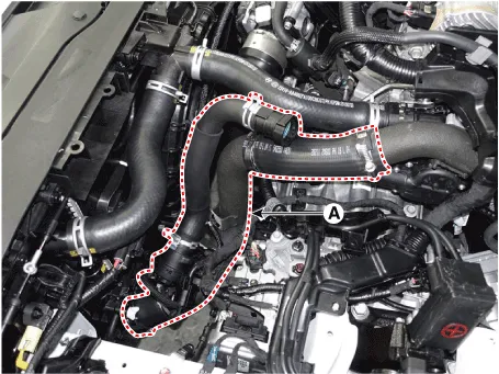
| 13. | Remove the intercooler inlet hose and pipe.
|
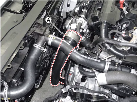
| 14. | Remove the intercooler outlet hose and pipe.
|


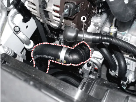
| 15. | Disconnct the radiator upper hose (A).
|
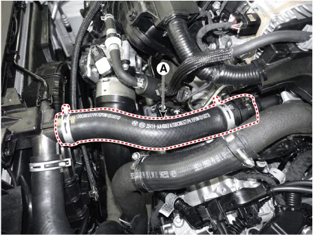
| 16. | Disconnct the radiator lower hose (A).
|
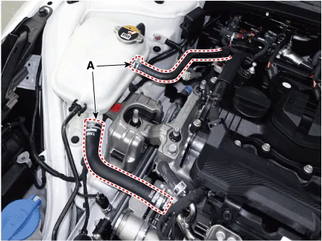
| 17. | Disconnect the coolant reservoir tank water hoses (A).
|
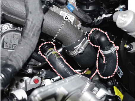
| 18. | Disconnect the heater hoses (A).
|
| 19. | Remove the universal joint from the shaft joint (Refer to Steering System - "Steering column & shaft") |
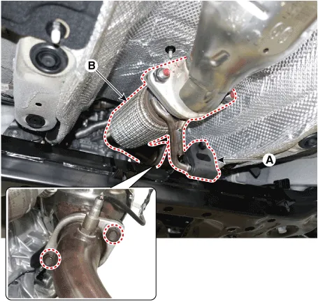
| 20. | Remove the front muffler heat protector (A).
|
| 21. | Loosen the hanger (A) and then remove the front muffler (B).
|
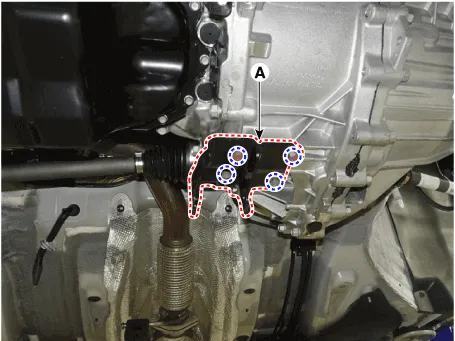
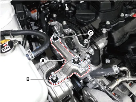
| 22. | Remove the roll rod bracket (A).
|
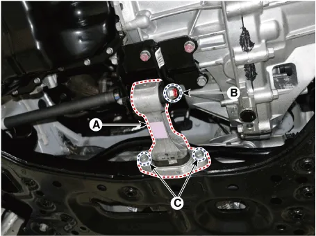
| 23. | Remove the roll rod mounting support bracket (A).
|
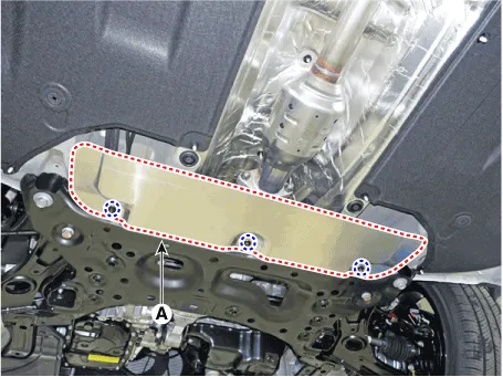
| 24. | Remove the sub frame. (Refer to Suspension System - "Sub frame") |
| 25. | Support the engine and transaxle assembly safely with a floor jack.
|
| 26. | Remove the engine mounting support bracket (A).
|
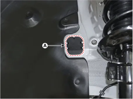
| 27. | Remove the service cover (A).
|
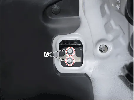
| 28. | Remove the transaxle mounting bolts (A).
|
| 29. | Remove the engine and transaxle assembly from a vehicle by slowly lifting off the vehicle.
|
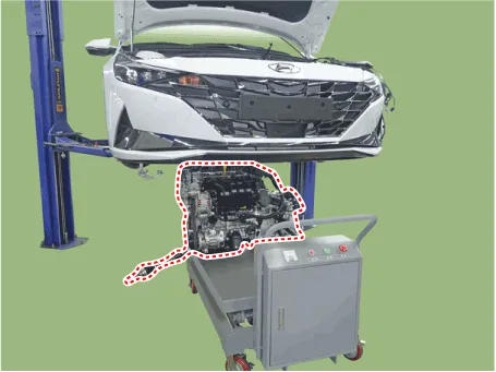
| 30. | Install in the reverse order of removal.
|
Components and components location Components1. Engine mounting bracket 2. Engine mounting support bracket3. Roll road braket4. Transaxle mounting bracket Repair procedures Removal and InstallationEngine mounting bracket1.
Drive Belt Repair procedures Removal and Installation* There are two methods to when removing the drive belt. [When removing the drive belt from the top of the vehicle] 1.
Other information:
Hyundai Elantra (CN7) 2021-2026 Service Manual: Special service tools
S
Hyundai Elantra (CN7) 2021-2026 Service Manual: General safety information and caution
General Safety Information and Caution1.Be careful when driving the vehicle using the smart cruise control system as follows.(1)On curves or inclines/declines• The smart cruise control system may have limits to detect distance to the vehicle ahead due to road and traffic conditions.
Categories
- Manuals Home
- Hyundai Elantra Owners Manual
- Hyundai Elantra Service Manual
- Specifications
- Troubleshooting
- Shift-lock release
- New on site
- Most important about car

Copyright © 2026 www.helantra7.com - 0.0203