
Hyundai Elantra (CN7): Engine And Transaxle Assembly / Engine Mounting
Components and components location
| Components |

| 1. Engine mounting bracket 2. Engine mounting support bracket | 3. Roll road braket 4. Transaxle mounting bracket |
Repair procedures
| Removal and Installation |
| 1. | Remove the engine room under cover. (Refer to Engine and Transaxle Assembly - "Engine Room Under Cover") |
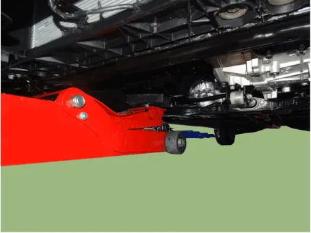
| 2. | Install the jack to the edge of oil pan.
|

| 3. | Remove the engine mounting support bracket (A).
|
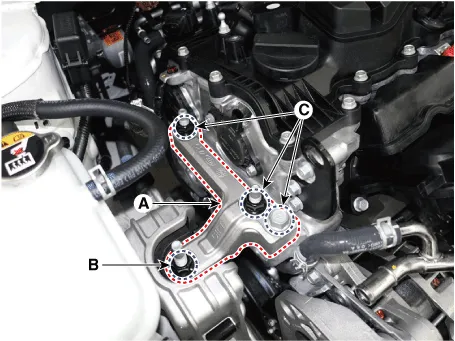
| 4. | Loosen the coolant reservoir tank (A) mounting bolts to obtain engine mounting working space.
|

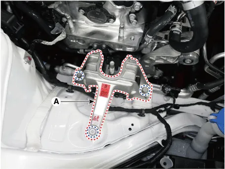
| 5. | Remove the engine mounting bracket (A).
|
| 6. | Installation is in the reverse order of removal. |
| 1. | Disconnect the negative battery terminal. |
| 2. | Remove the engine room under cover. (Refer to Engine and Transaxle Assembly - "Engine Room Under Cover") |
| 3. | Remove the air duct and air cleaner assembly. (Refer to Intake and Exhaust System - "Air Cleaner") |
| 4. | Remove the battery and battery tray. (Refer to Engine Electrical System - "Battery") |
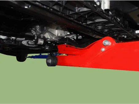
| 5. | Place the jack under the transaxle.
|
| 6. | Remove the service cover (A).
|
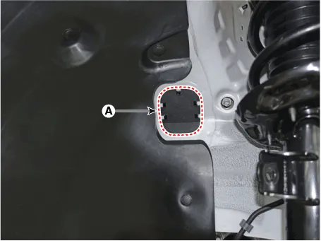
| 7. | Loosen the transaxle support bracket mounting bolts (A).
|
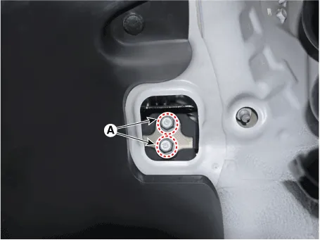
| 8. | Remove the transaxle mounting bracket (A).
|
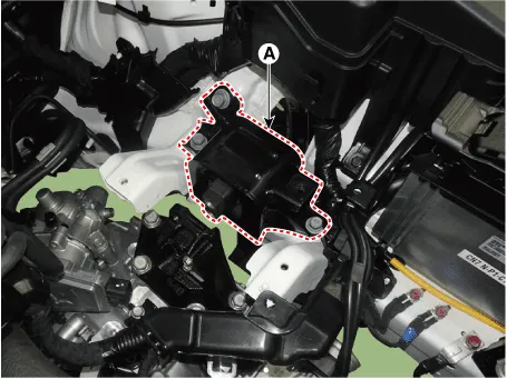
| 9. | Installation is in the reverse order of removal. |
| 1. | Remove the roll rod bracket (A).
|
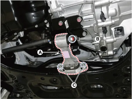
| 2. | Remove the roll rod support bracket (A).
|
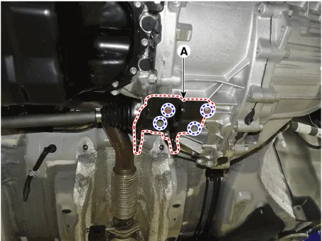
| 3. | Installation is in the reverse order of removal. |
Repair procedures Removal and Installation1.Remove the engine room under cover (A). Tightening torque : 7.8 - 11.8 N.m (0.8 - 1.2 kgf.
Repair procedures Removal • Use fender covers to avoid damaging painted surfaces.• To avoid damage, unplug the wiring connectors carefully while holding the connector portion.
Other information:
Hyundai Elantra (CN7) 2021-2026 Service Manual: Photo Sensor
Description and operation Description 1.The photo sensor is located at the center of the defrost nozzles.2.The photo sensor contains a photovoltaic (sensitive to sunlight) diode. The solar radiation received by its light receiving portion, generates an electromotive force in proportion to the amount of radiation received which is transferred to
Hyundai Elantra (CN7) 2021-2026 Service Manual: Description and operation
DescriptionRear Corner Radar is a system that measures the relative speed and distance from the following vehicles by using two electromagnetic wave radar sensors attached to the rear bumper, and detects any vehicle within the blind spot zone and gives off alarm.
Categories
- Manuals Home
- Hyundai Elantra Owners Manual
- Hyundai Elantra Service Manual
- Vehicle Information
- Troubleshooting
- Rear Seats
- New on site
- Most important about car
