Hyundai Elantra (CN7): Engine And Transaxle Assembly / Engine Room Under Cover
Repair procedures
| Removal and Installation |
| 1. | Remove the engine room under cover (A).
|
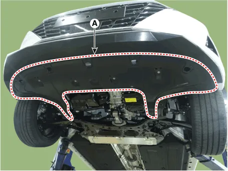
| 2. | Installation is reverse order of removal. |
Repair procedures Removal and Installation1.Remove the engine cover (A).2.Installation is reverse order of removal
Components and components location Components1. Engine mounting bracket 2. Engine mounting support bracket3. Roll road braket4. Transaxle mounting bracket Repair procedures Removal and InstallationEngine mounting bracket1.
Other information:
Hyundai Elantra (CN7) 2021-2026 Service Manual: License Lamps
Repair procedures Removal1.Disconnect the negative (-) battery terminal.2.Push the lock pin (B) and remove the license lamp (A).3.Disconnect the license lamp connector (A).4.Replace the bulb (A).Installation1.Connect the license lamp connector.2.Install the license lamp.
Hyundai Elantra (CN7) 2021-2026 Service Manual: General safety information and caution
General Safety Information and Caution1.Be careful when driving the vehicle using the smart cruise control system as follows.(1)On curves or inclines/declines• The smart cruise control system may have limits to detect distance to the vehicle ahead due to road and traffic conditions.
Categories
- Manuals Home
- Hyundai Elantra Owners Manual
- Hyundai Elantra Service Manual
- Front Bumper
- Engine Mechanical System
- General Tightening Torque Table. General information
- New on site
- Most important about car
