Hyundai Elantra (CN7): Engine And Transaxle Assembly / Engine Cover
Repair procedures
| Removal and Installation |
| 1. | Remove the engine cover (A).
|
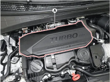
| 2. | Installation is reverse order of removal |
Repair procedures Removal and Installation1.Remove the engine room under cover (A). Tightening torque : 7.8 - 11.8 N.m (0.8 - 1.2 kgf.
Other information:
Hyundai Elantra (CN7) 2021-2026 Service Manual: Auto Defogging Sensor
Description DescriptionThe auto defogging sensor is installed on the front window glass. The sensor judges and sends signal if moisture occurs to blow out wind for defogging. The air conditioner control module receives signal from the sensor and restrains moisture and eliminate defog by controlling the intake actuator, A/C, auto defogging actuat
Hyundai Elantra (CN7) 2021-2026 Service Manual: Heater & A/C Control Unit (Manual)
Components and components location Components[This illustration shows the LHD type. RHD type is symmetrical.][Connector A] Pin No Function Pin No Function 1Low (Register specifications)4Middle Low (Register specifications)2Common (Register
Categories
- Manuals Home
- Hyundai Elantra Owners Manual
- Hyundai Elantra Service Manual
- Front Radar Unit
- Specifications
- Vehicle Information
- New on site
- Most important about car
