Hyundai Elantra (CN7): Engine Control System / Knock Sensor (KS)
Description and operation
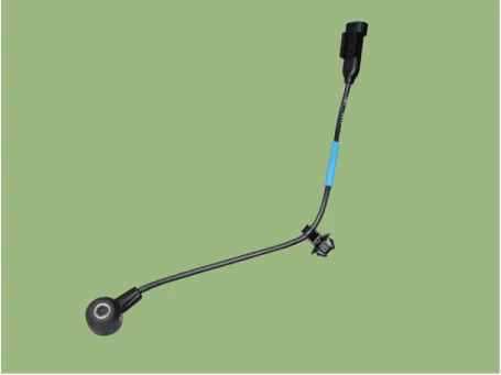
Knocking is a phenomenon characterized by undesirable vibration and noise and can cause engine damage.
Knock Sensor (KS) is installed on the cylinder block and senses engine knocking. When knocking occurs, the vibration from the cylinder block is applied as pressure to the piezoelectric element. At this time, this sensor transfers the voltage signal higher than the specified value to the ECM and the ECM retards the ignition timing.
Specifications
Item
|
Specification
|
Capacitance (pF)
| 850 - 1150
|
Resistance (MΩ)
| R > 1
|
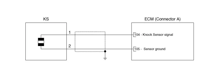
Schematic diagrams
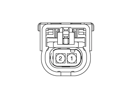
Harness Connector
Repair procedures
| 1. | Turn ignition switch OFF and disconnect the battery negative (-) terminal |
| 2. | Disconnect the knock sensor connector (A). 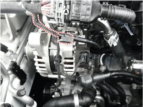
|
| 3. | Remove the installation bolt (A), and then remove the sensor from the cylinder block. Tightening Torque : 18.6 - 24.5 N.m (1.9 - 2.5 kgf.m, 13.7 - 18.1 lb-ft) |

|
| •
| Install the component with the specified torques. |
| •
| Note that internal damage may occur when the component is dropped. In this case, use it after inspecting. |
|
| 1. | Install in the reverse order of removal. |
Description and operation
DescriptionCamshaft Position Sensor (CMPS) is a hall sensor and detects the camshaft position by using a hall element.It is related with Crankshaft Position Sensor (CKPS) and detects the piston position of each cylinder which the CKPS can't detect.
Description and operation
DescriptionHeated Oxygen Sensor (HO2S) consists of the zirconium and the alumina and is installed on upstream and downstream of the Manifold Catalyst Converter (MCC).
Other information:
Description and operation
DescriptionThe auto defogging sensor is installed on front window glass. The sensor judges and sends signal if moisture occurs to blow out wind for defogging. The air conditioner control module receives a signal from the sensor and restrains moisture and eliminates defog by the intake actuator, A/C, auto defogging actua
Diagnosis with Diagnostic tool1.In the body electrical system, failure can be quickly diagnosed by using the vehicle diagnostic system (Diagnostic tool).The diagnostic system (Diagnostic tool) provides the following information.(1)Fault Code Searching : Checking failure and code number (DTC)(2)Data Analysis : Checking the system input/output data s

