Hyundai Elantra (CN7): Engine Control System / Heated Oxygen Sensor (HO2S)
Description and operation
Heated Oxygen Sensor (HO2S) consists of the zirconium and the alumina and is installed on upstream and downstream of the Manifold Catalyst Converter (MCC).
In order that this sensor normally operates, the temperature of the sensor tip is higher than 370°C (698°F). So it has a heater which is controlled by the ECM duty signal.
When the exhaust gas temperature is lower than the specified value, the heater warms the sensor tip.

Specifications
[Bank 1 / Sensor 1]
Item
|
Specification
|
Heater Resistance (Ω)
| Approx. 2.5 [20°C (68°F)]
|
[Bank 1 / Sensor 2]
Item
|
Specification
|
Heater Resistance (Ω)
| Approx. 3.0 [20°C (68°F)]
|
Schematic diagrams

Harness Connector
HO2S [Bank 1 / Sensor 1]

HO2S [Bank 1 / Sensor 2]

Repair procedures
| 1. | Turn the ignition switch OFF. |
| 2. | Disconnect the HO2S connector. |
| 3. | Measure resistance between HO2S heater terminals 2 and 5. [B1 / S1] Measure resistance between HO2S heater terminals 3 and 4. [B1 / S2] |
| 4. | Check that the resistance is within the specification. [Bank 1 / Sensor 1]
Item
| Specification
| Heater Resistance (Ω)
| Approx. 2.5 [20°C (68°F)]
|
[Bank 1 / Sensor 2]
Item
| Specification
| Heater Resistance (Ω)
| Approx. 3.0 [20°C (68°F)]
|
|
| 1. | Turn ignition switch OFF and disconnect the battery negative (-) terminal. |
| 2. | Disconnect the heated oxygen sensor connector (A). |
| 3. | Remove the heated oxygen sensor (B). Tightening Torque : 39.2 - 49.0 N.m (4.0 - 5.0 kgf.m, 28.9 - 36.1 lb-ft) |
| •
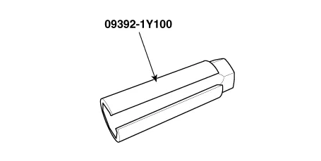
| Note that the SST (Part No. : 09392-2H100 or 09392-1Y100) is useful when removing the heated oxygen sensor. |
|
HO2S [Bank 1 / Sensor 1] 
HO2S [Bank 1 / Sensor 2] 

|
| •
| Install the component with the specified torques. |
| •
| Note that internal damage may occur when the component is dropped. In this case, use it after inspecting. |
|
| •
| DON’T use a cleaner, spray, or grease to sensing element and connector of the sensor because oil component in them may malfunction the sensor performance. |
| •
| Sensor and its wiring may be damaged in case of contacting with the exhaust system (Exhaust Manifold, Catalytic Converter, and so on). |
|
| 1. | Install in the reverse order of removal. |
Description and operation
DescriptionKnocking is a phenomenon characterized by undesirable vibration and noise and can cause engine damage. Knock Sensor (KS) is installed on the cylinder block and senses engine knocking.
Description and operation
DescriptionAccelerator Position Sensor (APS) is installed on the accelerator pedal module and detects the rotation angle of the accelerator pedal.
Other information:
Components and components location
Components Location1. Refrigerant Pipe Assembly
Repair procedures
Replacement1.If the compressor is marginally operable, run the engine at idle speed, and let the air conditioning work for a few minutes, then shut the engine off.
Components and components location
Components1. BSD Indicator2. Side repeater lamp
Repair procedures
Inspection1.Disconnect the negative (-) battery terminal.2.Remove the front door trim.(Refer to Body - "Front door trim")3.Disconnect the power door mirror connector from the harness4.

