Hyundai Elantra (CN7): Engine Control System / Accelerator Position Sensor (APS)
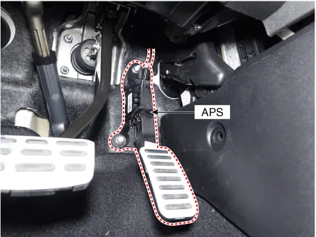
Description and operation
| Description |
Specifications
| Specification |
|
Accelerator Position
|
Output Voltage [V]
| |
|
APS1
|
APS2
| |
| C.T | 0.7 - 0.8 | 0.33 - 0.43 |
| W.O.T | 3.98 - 4.22 | 1.93 - 2.17 |
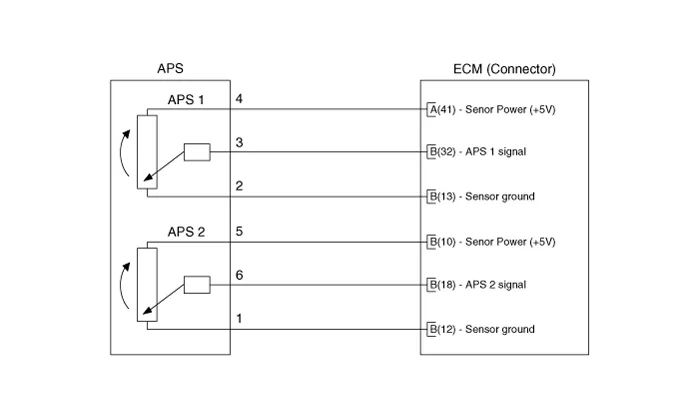
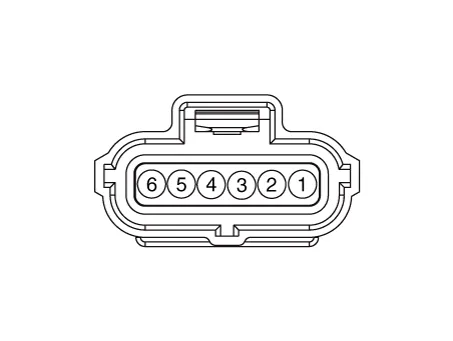
Schematic diagrams
| Circuit Diagram |
Repair procedures
| Inspection |
| 1. | Connect the diagnostic tool on the Data Link Connector (DLC). |
| 2. | Switch "ON" the ignition. |
| 3. | Measure the output voltage of the APS 3 and 6 at C.T and W.O.T.
|
| Removal |
| 1. | Turn ignition switch OFF and disconnect the battery negative (-) terminal. |
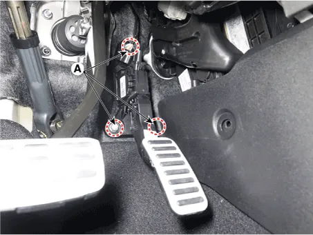
| 2. | Disconnect the accelerator position sensor connector (A).
|
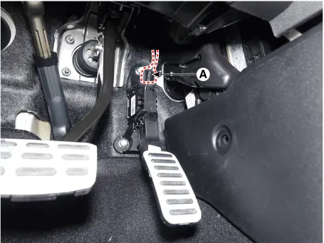
| 3. | Remove the accelerator pedal module after loosening the nut (A).
|
| Installation |
| 1. | Install in the reverse order of removal. |
Description and operation DescriptionHeated Oxygen Sensor (HO2S) consists of the zirconium and the alumina and is installed on upstream and downstream of the Manifold Catalyst Converter (MCC).
Description and operation DescriptionContinuous Variable Valve Timing (CVVT) system advances or retards the valve timing of the intake and exhaust valve in accordance with the ECM control signal which is calculated by the engine speed and load.
Other information:
Hyundai Elantra (CN7) 2021-2026 Service Manual: Description and operating principle
Description and OperationWireless Power Charger SystemDuring ACC or IG ON, battery voltage is supplied to the wireless power charger system to transmit an output of 5 W to mobile phone. Mobile phones certified with the wireless charging standard WPC (Qi 1.
Hyundai Elantra (CN7) 2021-2026 Service Manual: Troubleshooting
TroubleshootingDiagnosis with Diagnostic tool1.In the body electrical system, failure can be quickly diagnosed by using the vehicle diagnostic system (Diagnostic tool).The diagnostic system (Diagnostic tool) provides the following information.1)Fault Code Searching : Checking failure and code number (DTC)2)Data Analysis : Checking the system input/
Categories
- Manuals Home
- Hyundai Elantra Owners Manual
- Hyundai Elantra Service Manual
- Engine Mechanical System
- Front Bumper
- Repair procedures
- New on site
- Most important about car
