Hyundai Elantra (CN7): General Information / Lift and Support Points. General information
General information
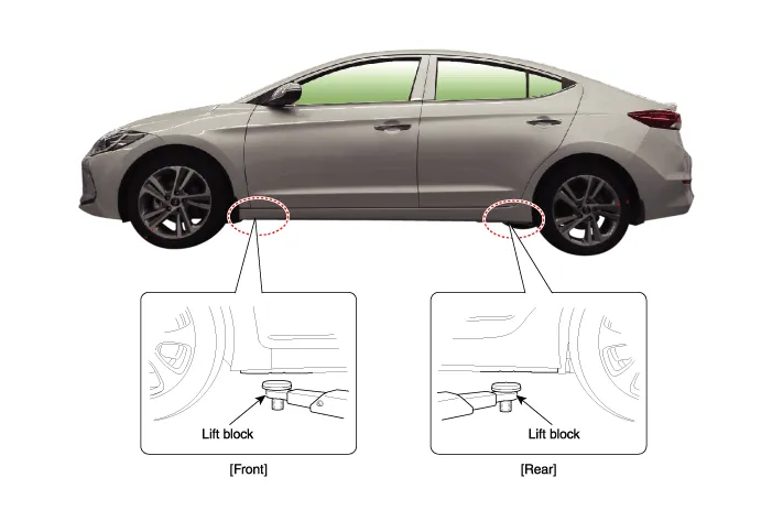
| Lift and Support Points |
|

|

| 1. | Place the lift blocks under the support points as shown in the illustration. |
| 2. | Raise the hoist a few inches (centimeters) and rock the vehicle to make sure that the vehicle is firmly supported. |
| 3. | Raise the hoist to full height to check whether the vehicle is firmly supported.
|
General information Warning and Caution Labels1. Radiator cap caution2. Fan caution3. Battery cautionAttentionSrs VehicleThis car is equipped with a supplemental restraint system.
General information TowingIf the vehicle needs to be towed, call a professional towing service. It is very dangerous to tow a vehicle with just a rope or chain.
Other information:
Hyundai Elantra (CN7) 2021-2026 Service Manual: Antenna Coil
Repair procedures Removal1.Disconnect the negative (-) battery terminal.2.Remove the crash pad lower panel.(Refer to Body - "Crash Pad Lower Panel")3.Remove the steering column shroud panel.(Refer to Body - "Steering Column Shroud Panel")4.Disconnect the immobilizer connector (A) and press the locking pin (B) using an awl.
Hyundai Elantra (CN7) 2021-2026 Service Manual: Mode Control Actuator
Description and operation DescriptionThe mode control actuator is located at the heater unit.It adjusts the position of the mode door by operating the mode control actuator based on the signal of the A/C control unit. Pressing the mode select switch makes the mode control actuator shift in order of Vent → Bi-Level → Floor → Mix.
Categories
- Manuals Home
- Hyundai Elantra Owners Manual
- Hyundai Elantra Service Manual
- Recommended Lubricants and Capacities
- Components and components location
- Rear Seats
- New on site
- Most important about car
