Hyundai Elantra (CN7): Power Door Mirrors / Power Door Mirror Switch
Hyundai Elantra (CN7) 2021-2026 Service Manual / Body Electrical System / Power Door Mirrors / Power Door Mirror Switch
Components and components location
| Components |

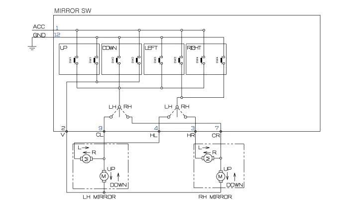
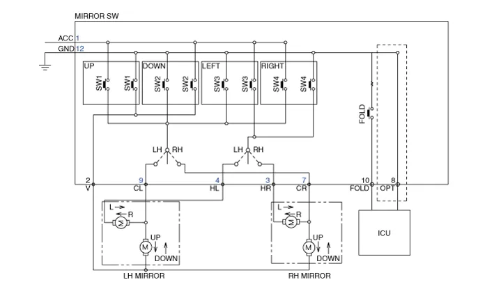
Schematic diagrams
| Circuit Diagram |
Without Mirror Folding
With Mirror Folding
Repair procedures
| Inspection |
[Power Window Switch]
| 1. | Disconnect the negative (-) battery terminal. |
| 2. | Remove the driver door trim. (Refer to Body - "Front Door Trim") |
| 3. | Disconnect the power mirror switch connector from the door trim.
|
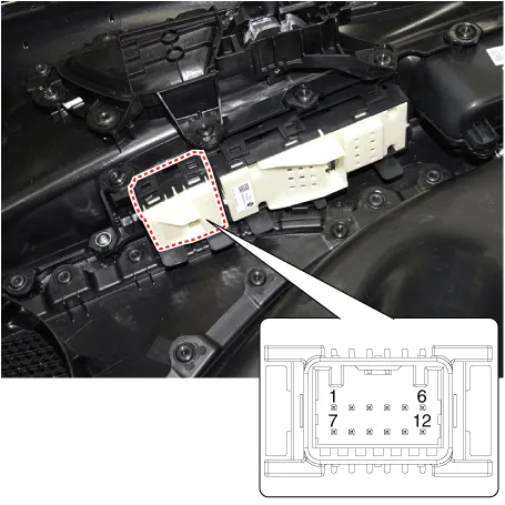
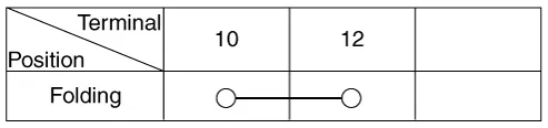
| 4. | Check for continuity between the terminals in each switch position according to the table. [Power Folding Mirror Switch]
|
| Removal |
| 1. | Disconnect the negative (-) battery terminal. |
| 2. | Remove the front door trim. (Refer to Body - "Front Door Trim") |
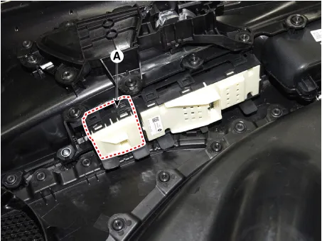
| 3. | Remove the power window assembly (A).
|
| Installation |
| 1. | Install the power window switch assembly. |
| 2. | Install the front door trim after connect the connector. |
| 3. | Connect the negative (-) battery terminal.
|

Component Location1. Power door mirror2. Power door mirror switch3. Power folding mirror switch
Repair procedures Removal1.Disconnect (-) battery terminal.2.Using a fastener remover (C), remove the mirror (A) as illustration below. • Protect mirror from removing tool with cloth (B) wrapped.
Other information:
Hyundai Elantra (CN7) 2021-2026 Service Manual: Special service tools
S
Hyundai Elantra (CN7) 2021-2026 Service Manual: Heater & A/C Control Unit (DATC)
Components and components location Components[This illustration shows the LHD type. RHD type is symmetrical.][Connector A] Pin No Function Pin No Function 1Battery9IGN22ILL+ (TAIL)10ISG Battery (+)3-11IGN14LIN BUS12HTD5-13-6-14-7-15-8RHEO (
Categories
- Manuals Home
- Hyundai Elantra Owners Manual
- Hyundai Elantra Service Manual
- Engine Mechanical System
- Engine Control / Fuel System
- Body (Interior and Exterior)
- New on site
- Most important about car

Copyright © 2026 www.helantra7.com - 0.0172