Hyundai Elantra (CN7): Power Door Mirrors / Power Door Mirror Actuator
Hyundai Elantra (CN7) 2021-2026 Service Manual / Body Electrical System / Power Door Mirrors / Power Door Mirror Actuator
Repair procedures
| Removal |
| 1. | Disconnect (-) battery terminal. |
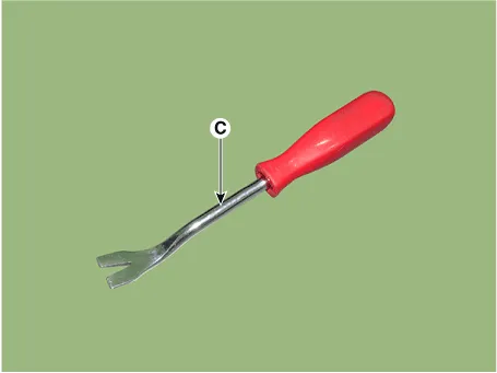
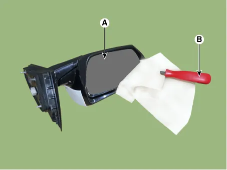
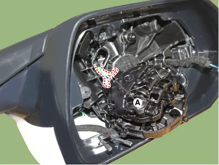
| 2. | Using a fastener remover (C), remove the mirror (A) as illustration below.
|

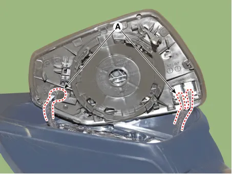
| 3. | Disconnect heat wire connectors (A) and then remove the mirror.
|
| 4. | Remove the mirror actuator (A) mounting screw.
|
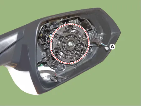
| 5. | Disconnect the connector (A) and then remove the mirror actuator.
|
| Installation |
| 1. | Connect the actuator connector and then install the mirror actuator. |
| 2. | Connect mirror heat wire connector and then install the mirror. |
| 3. | Connect (-) battery terminal then check if mirror works normally. |
Components and components location Components Schematic diagrams Circuit DiagramWithout Mirror FoldingWith Mirror Folding Repair procedures Inspection[Power Window Switch]1.
Components and components location Components1. Warning indicator2. Side repeater lamp Repair procedures Inspection1.Disconnect the negative (-) battery terminal.
Other information:
Hyundai Elantra (CN7) 2021-2026 Service Manual: Components and positions
C
Hyundai Elantra (CN7) 2021-2026 Service Manual: Description and operation
Description and OperationBlcok Diagram • This system monitors the driving situations through the radar and the camera. Thus, for a situation out of the sensing range, the system may not normally operate. The System may be limited when : • The radar sensor or camer
Categories
- Manuals Home
- Hyundai Elantra Owners Manual
- Hyundai Elantra Service Manual
- Driver assistance system
- Body Electrical System
- Brake bleeding procedures
- New on site
- Most important about car

Copyright © 2026 www.helantra7.com - 0.0226