
Hyundai Elantra (CN7): Power Door Mirrors / Power Door Mirror Assembly
Components and components location
| Components |
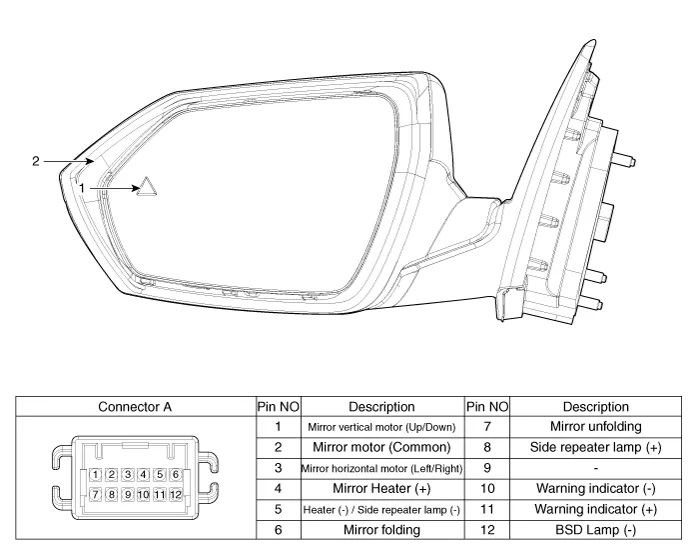
| 1. Warning indicator | 2. Side repeater lamp |
Repair procedures
| Inspection |
| 1. | Disconnect the negative (-) battery terminal. |
| 2. | Remove the front door quadrant inner cover (A).
|

| 3. | Disconnect the power door mirror connector from the harness.
|
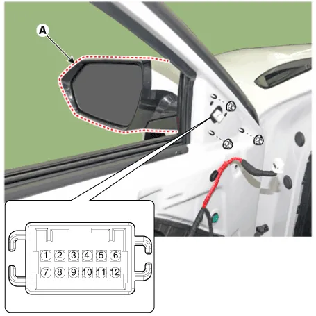
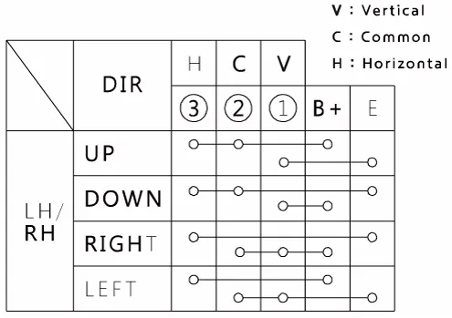
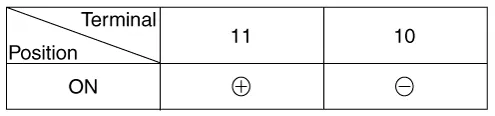
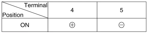
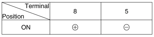
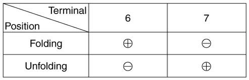
| 4. | Apply battery voltage to each terminal as shown in the table and verify that the mirror operates properly. [Mirror Control (LH/RT)]
[Warning indicator]
[Mirror Heater]
[Side Repeater Lamp]
[Mirror Fording Motor]
|
| Removal |
| 1. | Disconnect the negative (-) battery terminal. |
| 2. | Remove the front door trim. (Refer to Body - "Front door trim") |
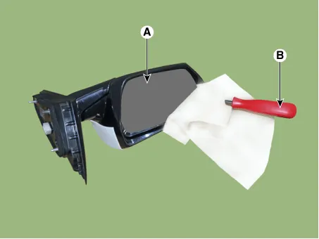
| 3. | Using a fastener remover (C), remove the mirror (A) as illustration below.
|


| 4. | Disconnect heat wire connectors (A) and then remove the mirror.
|
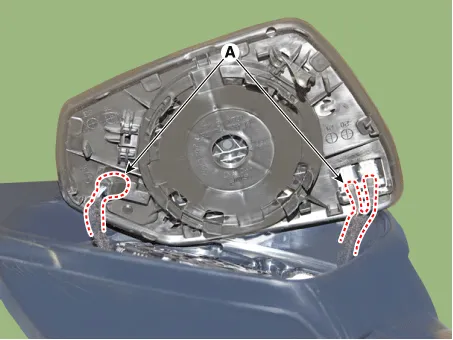
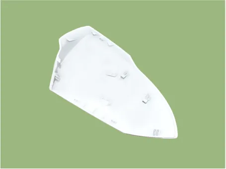
| 5. | Remove the scalp.
|
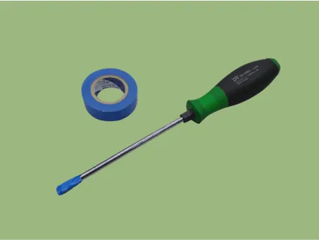
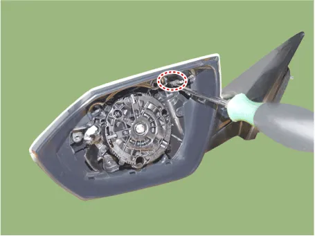
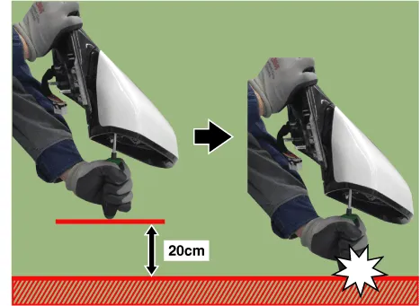
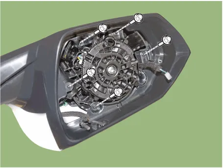
| 6. | Remove the fornt housing cover after loosening mounting screws.
|
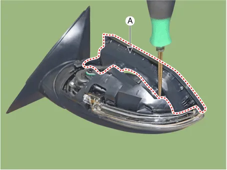
| 7. | Using a fastener remover, remove the LED side repeater lamp (A) as illustration below.
|
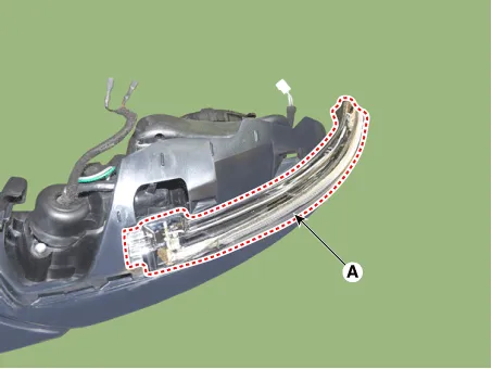
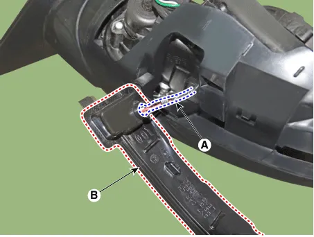
| 8. | Disconnect the connector (A) and then remove the LED side repeater lamp (B).
|
| Installation |
| 1. | Install the side repeater lamp. |
| 2. | Install the front housing cover.
|
| 3. | Install the scalp.
|
| 4. | Connect mirror wire connectors. |
| 5. | Install the door mirror assembly. |
| 6. | Connect (-) battery terminal then check if door mirror lamp works normally. |
Repair procedures Removal1.Disconnect (-) battery terminal.2.Using a fastener remover (C), remove the mirror (A) as illustration below. • Protect mirror from removing tool with cloth (B) wrapped.
Other information:
Hyundai Elantra (CN7) 2021-2026 Service Manual: Condenser
Components and components location Components Location[General type]1. Condenser[N Line]1. Condenser Repair procedures Inspection1.Check the condenser fins for clogging and damage. If clogged, clean them with water, and blow them with compressed air.
Hyundai Elantra (CN7) 2021-2026 Service Manual: Troubleshooting
Diagnosis with Diagnostic tool1.In the body electrical system, failure can be quickly diagnosed by using the vehicle diagnostic system (Diagnostic tool).The diagnostic system (Diagnostic tool) provides the following information.(1)Fault Code Searching : Checking failure and code number (DTC)(2)Data Analysis : Checking the system input/output data s
Categories
- Manuals Home
- Hyundai Elantra Owners Manual
- Hyundai Elantra Service Manual
- Drive Mode
- Specifications
- Engine Mechanical System
- New on site
- Most important about car
