
Hyundai Elantra (CN7): Seat Electrical / Power Seat Motor
Hyundai Elantra (CN7) 2021-2026 Service Manual / Body Electrical System / Seat Electrical / Power Seat Motor
Components and components location
| Component Location |
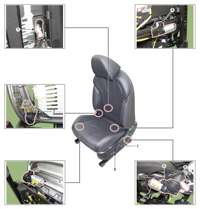
| 1. Lumber support motor 2. Reclining motor 3. Front height motor 4. Slide motor | 5. Rear height motor 6. Reclining limit switch 7. Lumber support switch 8. Seat switch |
Repair procedures
| Inspection |
Power Seat Motor
| 1. | Disconnect the connectors for each motor. [Slide Motor]
[Rear Height Motor]
[Front Height Motor]
[Reclining Motor]
[Lumbar Support Motor]
|
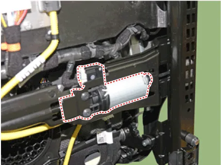
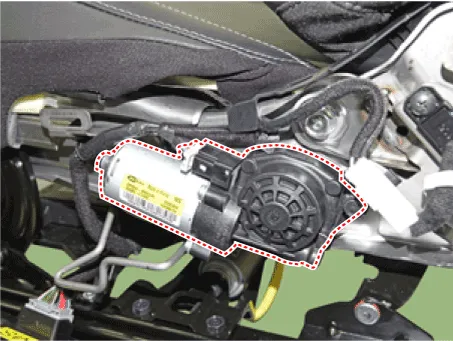
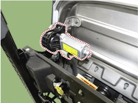
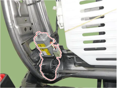
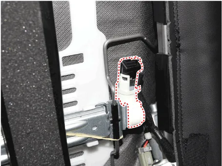
| 2. | With the battery connected directly to the motor terminals, check if the motors run smoothly. |
| 3. | Reverse the connections and check that the motor turns in reverse. |
| 4. | If there is an abnormality, replace the motors. |
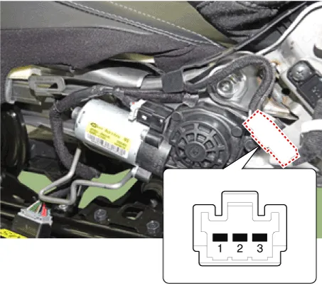
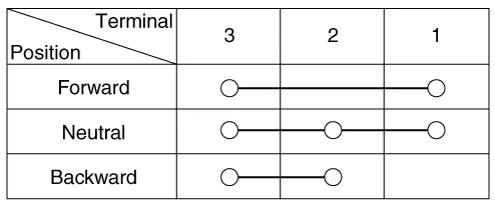
[Reclining Motor Limit Switch]
|

| 1. | Disconnect the limit switch and operate the limit switch. |
| 2. | Check for continuity between the terminals. |
| 3. | Make sure that the seat operation is normal in the reverse after the maximum operation. |
| 4. | If there is an abnormality, replace the limit switch.
|
| Remove |
Front Seat
| 1. | Disconnect the battery terminals. |
| 2. | Remove the front seat assembly. (Refer to Body - "Front Seat Assembly") |
Repair procedures Removal1.Disconnect the negative (-) battery terminal.2.Remove the front seat outer shield cover.(Refer to Body - "Front Seat Outer Shield Cover")3.
Other information:
Hyundai Elantra (CN7) 2021-2026 Service Manual: Condenser
Components and components location Components Location[General type]1. Condenser[N Line]1. Condenser Repair procedures Inspection1.Check the condenser fins for clogging and damage. If clogged, clean them with water, and blow them with compressed air.
Hyundai Elantra (CN7) 2021-2026 Service Manual: Parking Distance Warning (PDW)
Description and operation Description• PDW consists of 8 sensors (front : 4 units, rear : 4 units) that are used to detect obstacles and transmit the result in three separate warning levels, the first, second and third to IBU via LIN communication.
Categories
- Manuals Home
- Hyundai Elantra Owners Manual
- Hyundai Elantra Service Manual
- Driver assistance system
- Function settings
- Vehicle Information
- New on site
- Most important about car

Copyright © 2026 www.helantra7.com - 0.0159