Hyundai Elantra (CN7): Power Windows / Power Window Switch
Components and components location
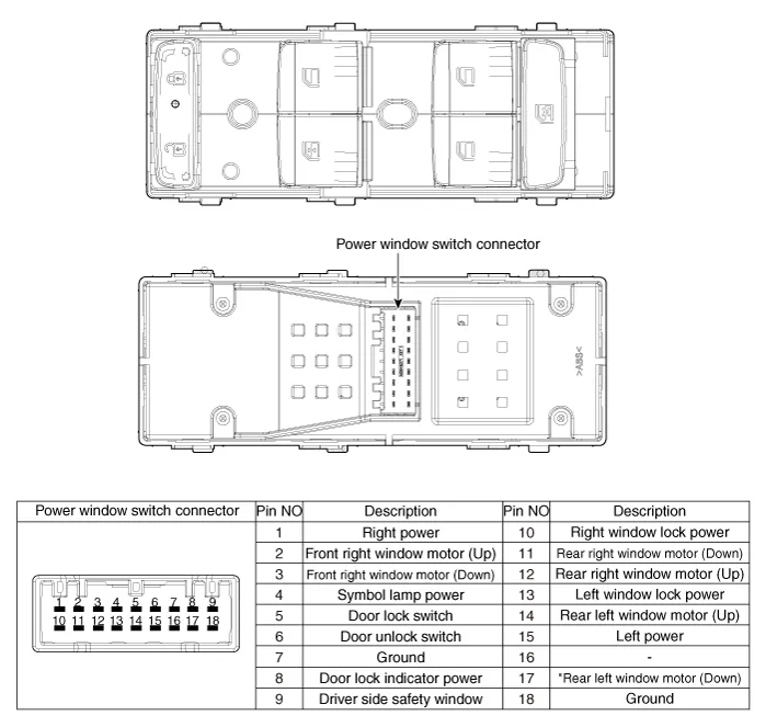
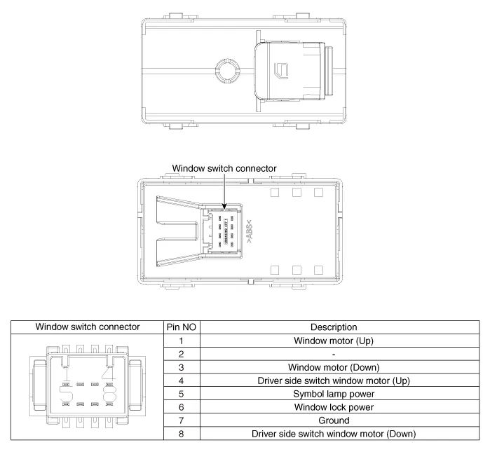
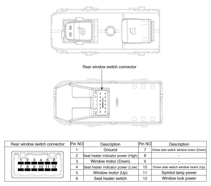
| Components |
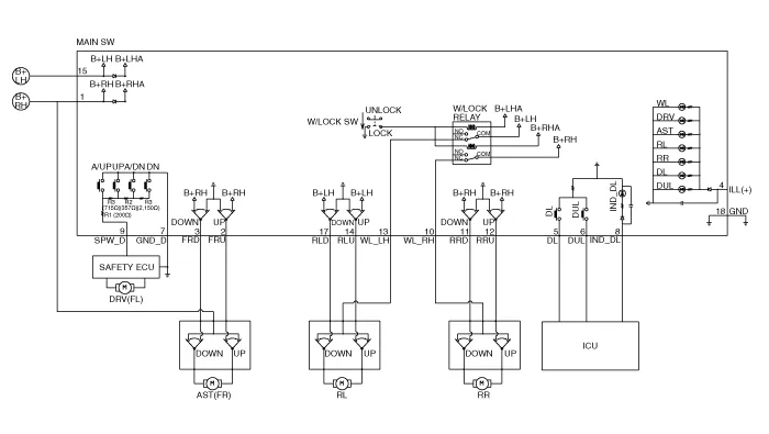
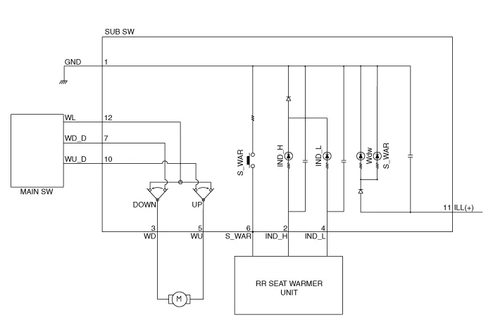
Schematic diagrams
| Circuit Diagram |
| [Auto down + Door lock] |
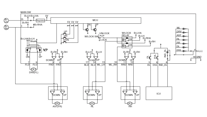
| [Driver side safety + Door lock] |
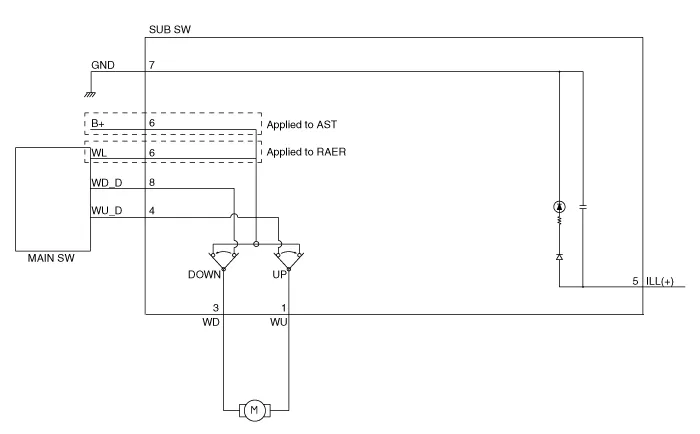
| [Non auto] |
| [Non auto + Seat heater] |
Repair procedures
| Removal |
| 1. | Disconnect the negative (-) battery terminal. |
| 2. | Remove the front door trim. (Refer to Body - "Front Door Trim") |
| 3. | Remove the power window switch (A).
|

| 1. | Disconnect the negative (-) battery terminal. |
| 2. | Remove the rear door trim. (Refer to Body - "Rear Door Trim") |
| 3. | Remove the power window switch assembly after disengaging the mounting clips.
|

| Installation |
| 1. | Install the power window switch assembly. |
| 2. | Install the front door trim after connect the connector. |
| 1. | Install the power window switch assembly. |
| 2. | Install the rear power window switch. |
Components and components location Components Schematic diagrams Circuit DiagramStandard type Repair procedures Inspection • Wrap the protective tape on the tool to disassemble with the screwdriver or remover.
Components and components location Component Location1. Integrated body control unit (IBU)2. Rear glass defogger switch3. Rear glass defogger Rear Glass Defogger Printed Heater Repair procedures Inspection • Wrap tin foil around the end of the voltmeter test lead to prevent damaging the heater line.
Other information:
Hyundai Elantra (CN7) 2021-2026 Service Manual: Smart Cruise Control (SCC) Switch
Schematic diagrams Circuit DiagramTRIP / SCC / LFA Repair procedures Inspection1.Check for resistance between terminals in each switch position (LH).[LH : Audio + Hands free] Switch Resistance (±5%) SEEK Up430 ΩSEEK Down1.
Hyundai Elantra (CN7) 2021-2026 Service Manual: Components and components location
C
Categories
- Manuals Home
- Hyundai Elantra Owners Manual
- Hyundai Elantra Service Manual
- Body Electrical System
- Drive Mode
- Troubleshooting
- New on site
- Most important about car
