Hyundai Elantra (CN7): Power Windows / Power Window Motor
Components and components location
| Components |

Schematic diagrams
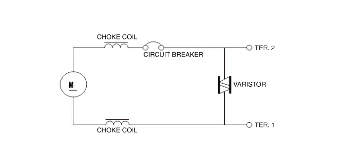
| Circuit Diagram |
Repair procedures
| Inspection |
|

| 1. | Disconnect the negative (-) battery terminal. |
| 2. | Remove the front door trim. (Refer to Body - "Front Door Trim") |
| 3. | Disconnect the motor connector from the motor.
|
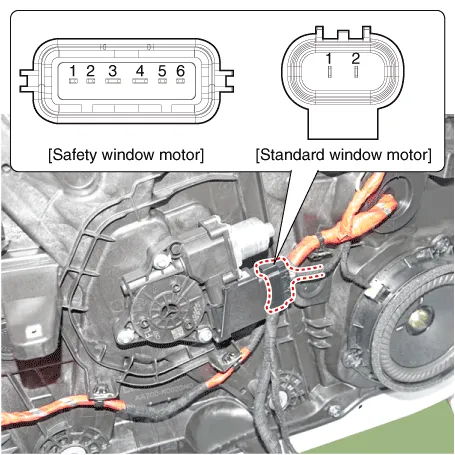
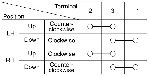
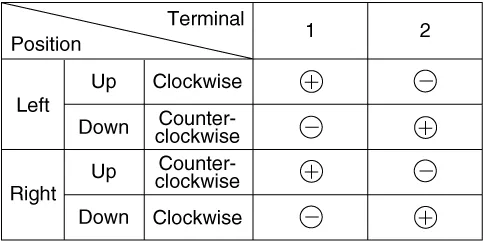
| 4. | Connect the terminal No.1 and No.2 to battery voltage (12V) and check that the motor operates smoothly when connecting the terminals below. [Safety Window Motor]
|
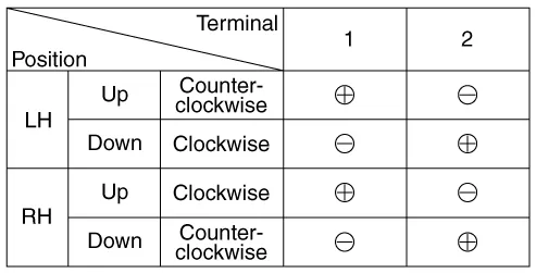
| 5. | Connect the motor terminals directly to battery voltage (12V) and check that the motor operates smoothly. Next, reverse the polarity and check that the motor operates smoothly in the reverse direction. If the operation is abnormal, replace the motor. [Standard Window Motor]
|
| 1. | Disconnect the negative (-) battery terminal. |
| 2. | Remove the rear door trim. (Refer to Body - "Rear Door Trim") |
| 3. | Disconnect the motor connector from the motor.
|
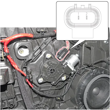
| 4. | Connect the motor terminals No.1 and No.2 directly to battery voltage (12V) and check that the motor operates smoothly. If the operation is abnormal, replace the motor. [Safety Window Motor]
|
Component Location1. DDM (Driver Door Module)2. ADM (Assistant Door Module)3. Front/Rear window motor4. RDM / RLDM (Rear Door Module)
Components and components location ComponentsDriver Power Window SwitchSub Power Window Switch (Passenger)Sub Power Window Switch (Rear) Schematic diagrams Circuit DiagramMain power window switch[Auto down + Door lock][Driver side safety + Door lock]Sub Power Window Switch (Passenger)Sub Power Window Switch (Rear)[Non auto][Non auto + Seat heater] Repair procedures RemovalDriver / Passenger Power Window Switch1.
Other information:
Hyundai Elantra (CN7) 2021-2026 Service Manual: Components and components location
C
Hyundai Elantra (CN7) 2021-2026 Service Manual: Special service tools
Special Service Tools Tool Name / Number Illustration Description LKA Compensator(09890-3V100)Used for compensating front view camera unitBCW Sensor Correction Tool Set(09958-3T500)Used to correct the blind-spot radar unit.
Categories
- Manuals Home
- Hyundai Elantra Owners Manual
- Hyundai Elantra Service Manual
- Auto Hold. Warning messages
- Troubleshooting
- Engine Control / Fuel System
- New on site
- Most important about car
