Hyundai Elantra (CN7): Front Radar System / Smart Cruise Control (SCC) Switch
Schematic diagrams
| Circuit Diagram |

Repair procedures
| Inspection |
| 1. | Check for resistance between terminals in each switch position (LH).
[LH : Audio + Hands free]
|

| 2. | Check for resistance between terminals in each switch position (RH).
[Cruise]
[Trip]
|
| Removal |
| 1. | Disconnect the negative (-) battery terminal. |
| 2. | Remove the steering wheel assembly. (Refer to Steering System - "Steering Wheel") |
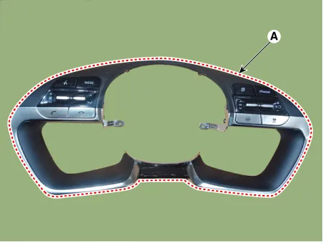
| 3. | Remove the steering back cover (A).
|

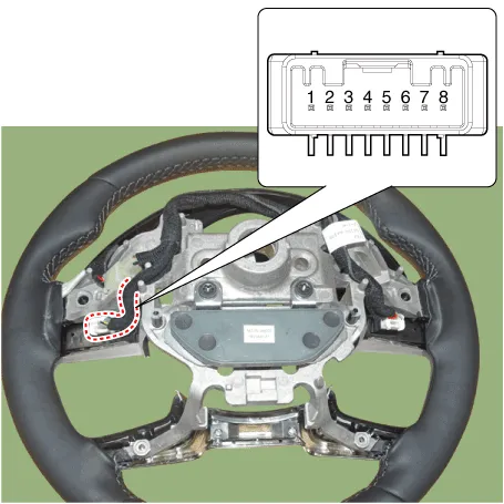
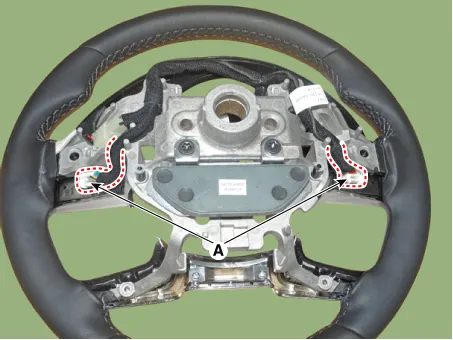
| 4. | Remove the steering remote control connector (A).
|
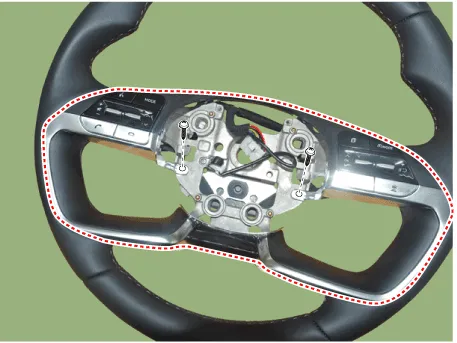
| 5. | Remove the steering remote control(Switch (A)) after loosening the screws.
|
| Installation |
| 1. | Install the steering wheel remote control after connecting the connector. |
| 2. | Install the steering wheel. |
| 3. | Connect the negative (-) battery terminal. |
Components and components location Components Location1. Front rader unit Specifications Specification Item Specification Power supply (V)12Operation voltage (V)9 - 16 Schematic diagrams Circuit DiagramTerminal function Pin No Terminal function 1GROUND2L-CAN HIGH3L-CAN LOW4C-CAN HIGH5C-CAN LOW6IGN Repair procedures InspectionInspection procedure for vehicle with Forward Collision-Avoidance Assist and Smart Cruise Control system failure 1.
Other information:
Hyundai Elantra (CN7) 2021-2026 Service Manual: Head Lamp Leveling Device
Components and components location Component Location1. Head lamp leveling actuator2. Head lamp leveling switch Head Lamp Leveling Switch Schematic diagrams Schematic Diagrams Repair procedures Replacement1.Disconnect the negative (-) battery terminal.
Hyundai Elantra (CN7) 2021-2026 Service Manual: Auto Defogging Sensor
Description DescriptionThe auto defogging sensor is installed on the front window glass. The sensor judges and sends signal if moisture occurs to blow out wind for defogging. The air conditioner control module receives signal from the sensor and restrains moisture and eliminate defog by controlling the intake actuator, A/C, auto defogging actuat
Categories
- Manuals Home
- Hyundai Elantra Owners Manual
- Hyundai Elantra Service Manual
- Specifications
- Integrated Thermal Management Module (ITM)
- Rear Seats
- New on site
- Most important about car
