Hyundai Elantra (CN7): Driveshaft and axle / Rear Axle Assembly. Rear Hub - Carrier
Hyundai Elantra (CN7) 2021-2026 Service Manual / Driveshaft and axle / Rear Axle Assembly. Rear Hub - Carrier
Components and components location
| Components |
[Rear disc brake type]
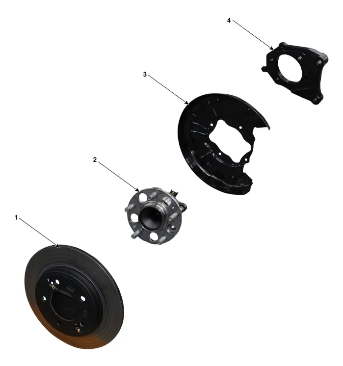
| 1. Rear brake disc 2. Hub bearing assembly | 3. Dust cover 4. Rear carrier |
[Rear drum brake type]
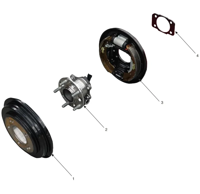
| 1. Rear drum 2. Rear hub assembly | 3. Brake assembly 4. Spacer |
Repair procedures
| Removal |
[Rear disc brake type]
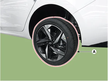
| 1. | Loosen the wheel nuts slightly. Raise the vehicle, and make sure it is securely supported. |
| 2. | Remove the rear wheel and tire (A) from the rear hub.
|

| 3. | Remove the rear brake caliper. (Refer to Brake System - "Rear Disc Brake") |
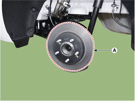
| 4. | Loosen the screw and the remove the rear break disc (A).
|
| 5. | Disconnect the rear wheel speed sensor connector (A).
|
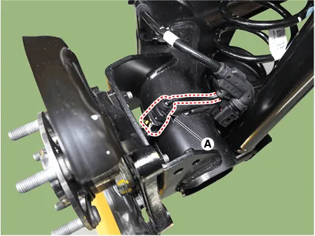
| 6. | Remove the hurb bearing assembly after loosening the hurb bearing mounting bolts (A).
|
| 7. | Separate the backing plate and extra bracket after loosening the mounting bolts.
|

[Rear drum brake type]
| 1. | Loosen the wheel nuts slightly. Raise the vehicle, and make sure it is securely supported. |
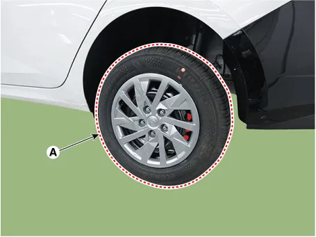
| 2. | Remove the rear wheel and tire (A) from the rear hub.
|
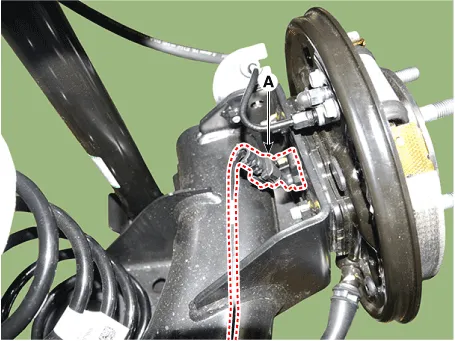
| 3. | Disconnect the rear wheel speed sensor connector (A).
|
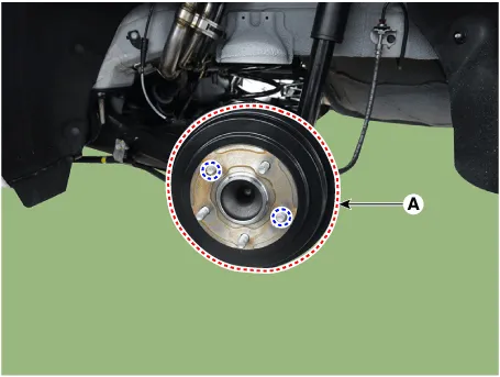
| 4. | Loosen the screw and then remove the rear drum brake (A).
|
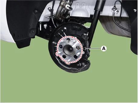
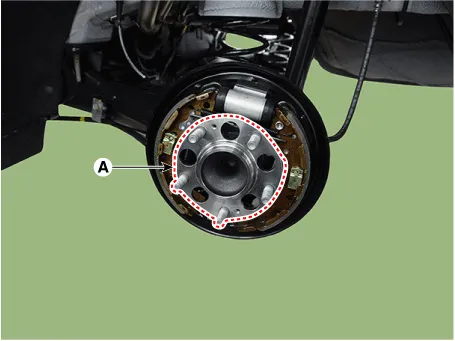
| 5. | Loosen the hub mounting bolts and then remove the hub (A) from the torsion beam.
|
| Inspection |
| 1. | Check the hub for cracks and the splines for wear. |
| 2. | Check the brake disc for scoring and damage. |
| 3. | Check the rear axle carrier for cracks. |
| 4. | Replace only the sensor cap when the warning light turns on due to a defective sensor cap of the hub bearing. (Refer to Brake System - "Rear Wheel Speed Sensor") |
| Installation |
| 1. | To install, reverse the removal procedures. |
Repair procedures RemovalThe type can replace the wheel side joint boot1.Remove the front drive shaft.(Refer to Driveshaft Assembly - "Front Driveshaft")2.
Other information:
Hyundai Elantra (CN7) 2021-2026 Service Manual: Components and components location
C
Hyundai Elantra (CN7) 2021-2026 Service Manual: Troubleshooting
TroubleshootingDiagnosis with Diagnostic tool1.In the body electrical system, failure can be quickly diagnosed by using the vehicle diagnostic system (Diagnostic tool).The diagnostic system (Diagnostic tool) provides the following information.1)Fault Code Searching : Checking failure and code number (DTC)2)Data Analysis : Checking the system input/
Categories
- Manuals Home
- Hyundai Elantra Owners Manual
- Hyundai Elantra Service Manual
- General Tightening Torque Table. General information
- Rear Seats
- Engine Mechanical System
- New on site
- Most important about car

Copyright © 2026 www.helantra7.com - 0.0136