Hyundai Elantra (CN7): IMS(Integrated Memory System) / Schematic diagrams
| Components |
Specifications[Memory Power Seat Unit ] Item Specifications Rated voltageDC 12VOperating VoltageDC 9V - 16VOperating Temperature Range-30°C to 75°C Dark currentMax.
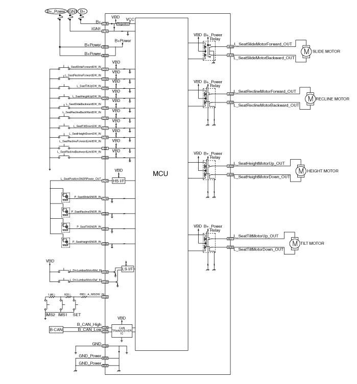
Components and components location ComponentsConnector Pin Information Pin no Connector A Connector B Connector C 1-B (+)Slide switch signal (Forward)2Reclining motor (Forward)GND(Power)Reclining switch signal (Forward)3Height motor (Up)B (+)Front tilt switch signal (Up)4Slide motor (Forward)-Height switch (Up)5-GNDReclining limit switch signal (Forward)6Reclining motor (Backward)B_CAN (High)7Tilt motor (Up)B_CAN (Low)8Tilt motor (Down)-9Height motor (Down)Driver lumber motor (Mid)10Slide motor (Backward)Seat slide sensor11Seat tilt sensor12-13Seat position sensor power14IGN 115Seat slide switch (Backward)16Seat recline switch (Backward)17Tilt switch (Down)18Height switch (Down)19Reclining limit switch signal (Backward)20GND21-22IMS Switch23Driver lumber motor (Def)24Reclining sensor25Height sensor26-27-28B(+) Schematic diagrams Circuit Diagram Repair procedures Removal1.
Other information:
Hyundai Elantra (CN7) 2021-2026 Service Manual: Heater Control Unit
Components and components location Component Location1. Heater control unitComponents[Connector A] Pin No Function Pin No Function 1Mode control actuator (Feedback)21Mode control actuator (Vent)2Intake actuator (Feedback)22Mode control actu
Hyundai Elantra (CN7) 2021-2026 Service Manual: Troubleshooting
TroubleshootingDiagnosis with Diagnostic tool1.In the body electrical system, failure can be quickly diagnosed by using the vehicle diagnostic system (Diagnostic tool).The diagnostic system (Diagnostic tool) provides the following information.1)Fault Code Searching : Checking failure and code number (DTC)2)Data Analysis : Checking the system input/
Categories
- Manuals Home
- Hyundai Elantra Owners Manual
- Hyundai Elantra Service Manual
- Specifications
- Driver assistance system
- General Tightening Torque Table. General information
- New on site
- Most important about car
