Hyundai Elantra (CN7): IMS(Integrated Memory System) / Memory power seat unit
Hyundai Elantra (CN7) 2021-2026 Service Manual / Body Electrical System / IMS(Integrated Memory System) / Memory power seat unit
Components and components location
| Components |
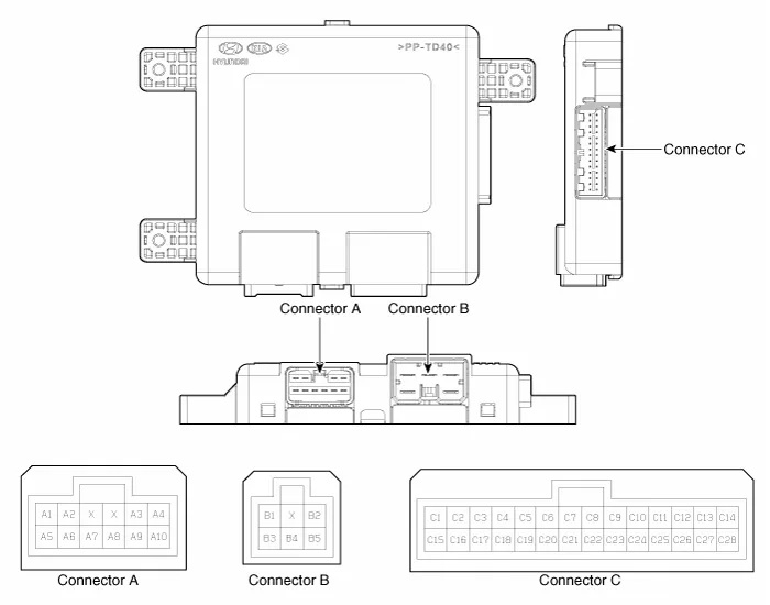
Connector Pin Information
|
Pin no
|
Connector A
|
Connector B
|
Connector C
|
| 1 | - | B (+) | Slide switch signal (Forward) |
| 2 | Reclining motor (Forward) | GND(Power) | Reclining switch signal (Forward) |
| 3 | Height motor (Up) | B (+) | Front tilt switch signal (Up) |
| 4 | Slide motor (Forward) | - | Height switch (Up) |
| 5 | - | GND | Reclining limit switch signal (Forward) |
| 6 | Reclining motor (Backward) | B_CAN (High) | |
| 7 | Tilt motor (Up) | B_CAN (Low) | |
| 8 | Tilt motor (Down) | - | |
| 9 | Height motor (Down) | Driver lumber motor (Mid) | |
| 10 | Slide motor (Backward) | Seat slide sensor | |
| 11 | Seat tilt sensor | ||
| 12 | - | ||
| 13 | Seat position sensor power | ||
| 14 | IGN 1 | ||
| 15 | Seat slide switch (Backward) | ||
| 16 | Seat recline switch (Backward) | ||
| 17 | Tilt switch (Down) | ||
| 18 | Height switch (Down) | ||
| 19 | Reclining limit switch signal (Backward) | ||
| 20 | GND | ||
| 21 | - | ||
| 22 | IMS Switch | ||
| 23 | Driver lumber motor (Def) | ||
| 24 | Reclining sensor | ||
| 25 | Height sensor | ||
| 26 | - | ||
| 27 | - | ||
| 28 | B(+) |
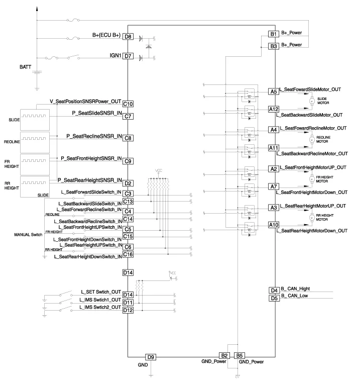
Schematic diagrams
| Circuit Diagram |
Repair procedures
| Removal |
| 1. | Disconnect the negative (-) battery terminal. |
| 2. | Remove the driver seat assembly. (Refer to Body - "Front Seat Assembly") |
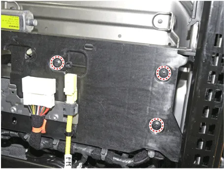
| 3. | Loosening the IMS unit mounting screws.
|
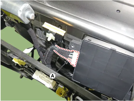
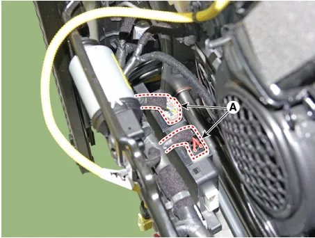
| 4. | Disconnect IMS module connectors (A) and then remove the IMS unit.
|
| Installation |
| 1. | Install the memory power seat unit. |
| 2. | Install the driver seat assembly. |
| 3. | Connect the negative (-) battery terminal. |
Components
Components and components location Components Repair procedures Removal1.Disconnect the negative (-) battery terminal.2.Remove the driver door trim.
Other information:
Hyundai Elantra (CN7) 2021-2026 Service Manual: Specifications
SpecificationAir Conditioner Item Specification CompressorTypeGamma 1.6 MPI, Gasoline 2.0 NU MPI, Gasoline 1.6 T-GDI : 6HVx14Gasoline 1.6 MPI : 6HVe14Oil type & CapacityFD46XG (IDEMITSU) 100 ± 10 g Pulley type6PK-TYPEDisplacement145 cc/revExpansion valveTypeBlock type RefrigerantTypeR - 134
Hyundai Elantra (CN7) 2021-2026 Service Manual: Description and operation
D
Categories
- Manuals Home
- Hyundai Elantra Owners Manual
- Hyundai Elantra Service Manual
- Brake System
- Troubleshooting
- Vehicle Information
- New on site
- Most important about car

Copyright © 2026 www.helantra7.com - 0.0158