Hyundai Elantra (CN7): IMS(Integrated Memory System) / Memory power seat switch
Components and components location
| Components |

Repair procedures
| Removal |
| 1. | Disconnect the negative (-) battery terminal. |
| 2. | Remove the driver door trim. (Refer to Body - "Front Door Trim") |
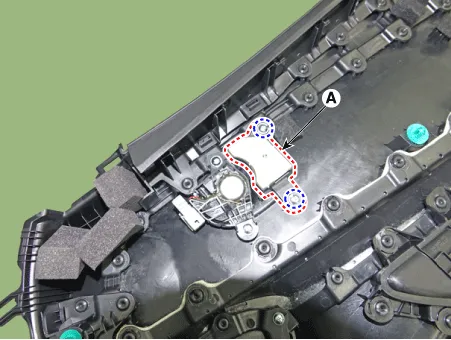
| 3. | Remove the memory power switch (A) after disengaging the mounting clips.
|
| Installation |
| 1. | Install the memory power seat control switch (IMS). |
| 2. | Install the door trim. |
| 3. | Connect the negative (-) battery terminal. |
| Inspection |
| 1. | Remove the memory power seat connector
|
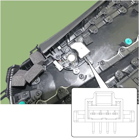
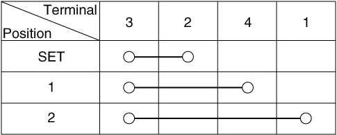
| 2. | When each switch is pressed, check the electricity flow between memory power seat switch connector and grounding, and if the electricity does not match the specification, replace the switch.
|
Components and components location ComponentsConnector Pin Information Pin no Connector A Connector B Connector C 1-B (+)Slide switch signal (Forward)2Reclining motor (Forward)GND(Power)Reclining switch signal (Forward)3Height motor (Up)B (+)Front tilt switch signal (Up)4Slide motor (Forward)-Height switch (Up)5-GNDReclining limit switch signal (Forward)6Reclining motor (Backward)B_CAN (High)7Tilt motor (Up)B_CAN (Low)8Tilt motor (Down)-9Height motor (Down)Driver lumber motor (Mid)10Slide motor (Backward)Seat slide sensor11Seat tilt sensor12-13Seat position sensor power14IGN 115Seat slide switch (Backward)16Seat recline switch (Backward)17Tilt switch (Down)18Height switch (Down)19Reclining limit switch signal (Backward)20GND21-22IMS Switch23Driver lumber motor (Def)24Reclining sensor25Height sensor26-27-28B(+) Schematic diagrams Circuit Diagram Repair procedures Removal1.
Other information:
Hyundai Elantra (CN7) 2021-2026 Service Manual: Turn Signal Lamp
Repair procedures Removal1.Disconnect the negative (-) battery terminal.2.Remove the front bumper.(Refer to Body - "Front Bumper Cover")3.Remove the head lamp.4.Remove the bulb socket (A) and turn signal lamp bulb (B) from the lamp assembly.Replacement1.
Hyundai Elantra (CN7) 2021-2026 Service Manual: Blower Resistor (Manual)
Repair procedures Inspection1.Measure the resistance between the terminals.2.The measured resistance is not within specification, the blower resistor must be replaced. (After removing the resistor)Replacement1.Disconnect the negative (-) battery terminal.
Categories
- Manuals Home
- Hyundai Elantra Owners Manual
- Hyundai Elantra Service Manual
- Vehicle Information
- Engine Mechanical System
- Maintenance
- New on site
- Most important about car
