Hyundai Elantra (CN7): Restraint / Seat Belt Pretensioner. Seat Belt Pretensioner (BPT)
Hyundai Elantra (CN7) 2021-2026 Service Manual / Restraint / Seat Belt Pretensioner. Seat Belt Pretensioner (BPT)
Description and operation
| Description |
The Seat Belt Pretensioners (BPT) are installed inside center pillar (LH & RH). When a vehicle crashes with a certain degree of frontal impact, the pretensioner seat belt helps to reduce the severity of injury to the front seat occupants by retracting the seat belt webbing. This prevents the front occupants from thrusting forward and hitting the steering wheel or the instrument panel when the vehicle crashes.
|

Components and components location
| Components |
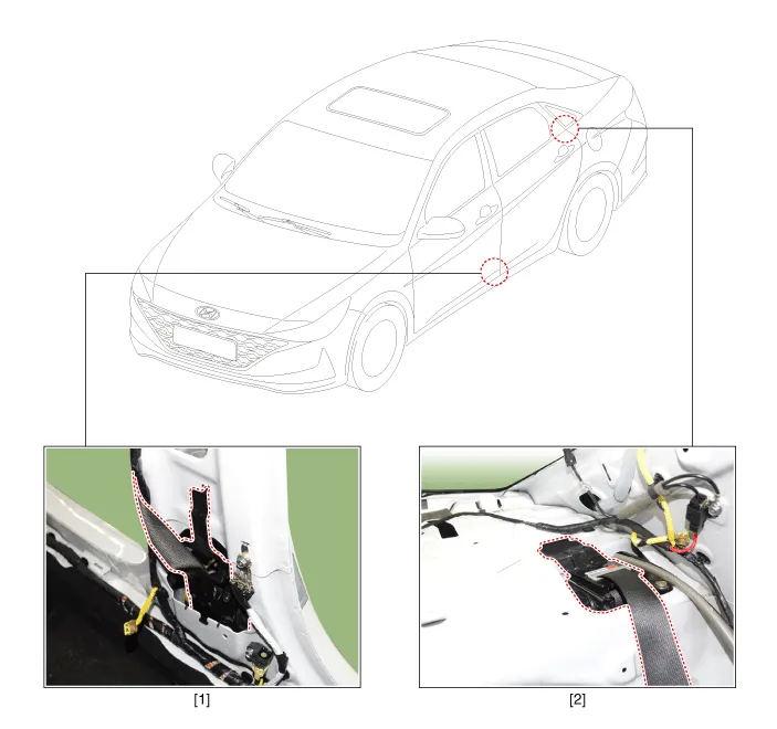
| 1. Front seat Belt Pretensioner (BPT) | 2. Rear seat Belt Pretensioner (BPT) |
Repair procedures
| Removal |
[Front Seat Belt Pretensioner (BPT)]
| 1. | Disconnect the negative (-) battery terminal. |
| 2. | Remove the door scuff trim. (Refer to Body (Interior and Exterior) - "Door Scuff Trim") |
| 3. | Remove the center pillar lower trim. (Refer to Body (Interior and Exterior) - "Center Pillar Trim") |
| 4. | Remove the center pillar upper trim. (Refer to Body (Interior and Exterior) - "Center Pillar Trim") |
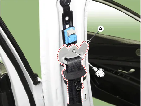
| 5. | Remove the front seat belt upper anchor (A) after loosening the mounting bolt.
|
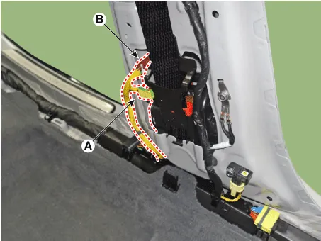
| 6. | Separate the BPT connector (A) and PSB connector (B).
|
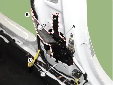
| 7. | Loosen the mounting bolts (B,C), remove the front seat belt pretensioner (A).
|
[Rear Seat Belt Pretensioner (BPT)]
| 1. | Remove the rear package tray trim. (Refer to Body (Interior and Exterior) - "Rear Package Tray Trim") |
| 2. | Disconnect the airbag connector (A) after pushing the lock pin.
|
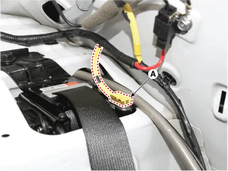
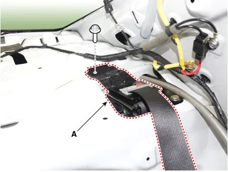
| 3. | Remove the rear seat belt pretensioner (A) after loosening the mounting bolt.
|
| Installation |
[Front Seat Belt Pretensioner (BPT)]
| 1. | Install the front seat belt pretensioner (A).
|
| 2. | Connect the BPT connector (A) and PSB connector (B).
|
| 3. | Install the front seat belt upper anchor (A) bolt.
|
| 4. | Install the center pillar upper trim. (Refer to Body (Interior and Exterior) - "Center Pillar Trim") |
| 5. | Install the center pillar lower trim. (Refer to Body (Interior and Exterior) - "Center Pillar Trim") |
| 6. | Install the door scuff trim. (Refer to Body (Interior and Exterior) - "Door Scuff Trim") |
| 7. | Reconnect the negative (-) battery terminal. |
| 8. | After installing the seat belt pretensioner, confirm proper system operation.
|

[Rear Seat Belt Pretensioner (BPT)]
| 1. | Tighten the mounting bolt and install the rear seat belt pretensioner (A).
|
| 2. | Connect the airbag connector (A).
|
| 3. | To install, reverse the removal procedures.
|
Description and operation Airbag Disposal When you scrap a vehicle equipped with an airbag, you must deploy it first.When you deploy an airbag, you need to have a skilled mechanic do the work.
Other information:
Hyundai Elantra (CN7) 2021-2026 Service Manual: Description and operation
DescriptionThe immobilizer system will disable the vehicle unless the proper ignition key is used, in addition to the currently available anti-theft systems such as car alarms, the immobilizer system aims to drastically reduce the rate of auto theft.1.
Hyundai Elantra (CN7) 2021-2026 Service Manual: Special service tools
S
Categories
- Manuals Home
- Hyundai Elantra Owners Manual
- Hyundai Elantra Service Manual
- Shift-lock release
- Body Electrical System
- Suspension System
- New on site
- Most important about car

Copyright © 2026 www.helantra7.com - 0.0111