Hyundai Elantra (CN7): Smart Key System / Smart key antenna
Repair procedures
| Removal |
|

| 1. | Disconnect the negative (-) battery terminal. |
| 2. | Remove the console assembly. (Refer to Body - "Floor Console Assembly") |
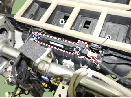
| 3. | Remove the interior 1 antenna (B) after loosening the mounting nuts and disconnecting the connector (A).
|
| 1. | Disconnect the negative (-) battery terminal. |
| 2. | Remove the console rear complete assembly. (Refer to Body - "Floor Console Assembly") |
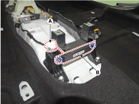
| 3. | Remove the interior 1 antenna (B) after loosening the mounting nuts (2EA) and disconnecting the connector (A).
|
| 1. | Disconnect the negative (-) battery terminal. |
| 2. | Remove the rear transverse trim (A).
|
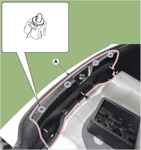
| 3. | Remove the interior 3 antenna (B) after loosening mounting screws and disconnecting the connector (A).
|
| 1. | Disconnect the negative (-) battery terminal. |
| 2. | Remove the rear bumper. (Refer to Body - "Rear Bumper Assembly") |
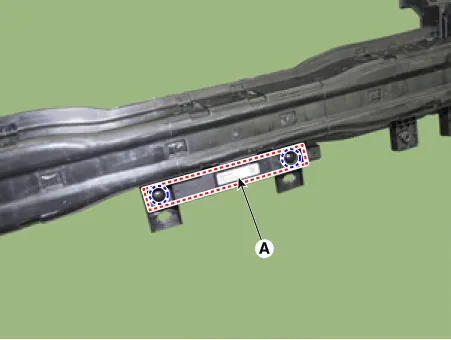
| 3. | Rremove the exterior bumper antenna (A) after loosening mounting nuts.
|
| 1. | Disconnect the negative (-) battery terminal. |
| 2. | Remove the front door trim. (Refer to Body - "Front Door Trim") |
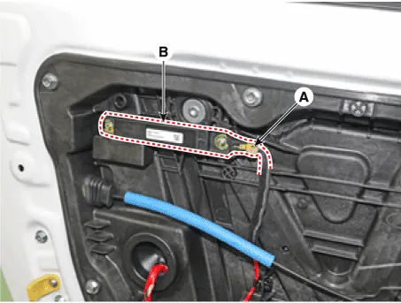
| 3. | Remove the front door antenna (B) after loosening mounting screws and disconnecting the connector (A).
|
| 1. | Disconnect the negative (-) battery terminal. |
| 2. | Remove the front left wheel guard. |
| 3. | Disconnect the connectors (A), then remove the buzzer (A).
|

| 1. | Disconnect the negative (-) battery terminal. |
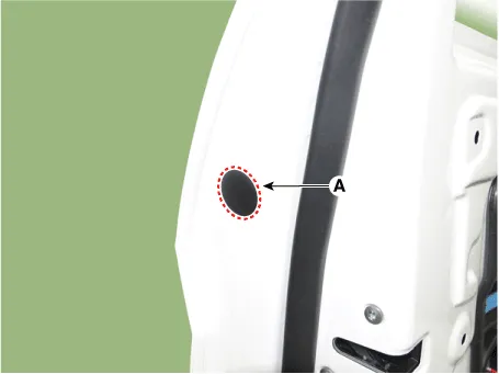
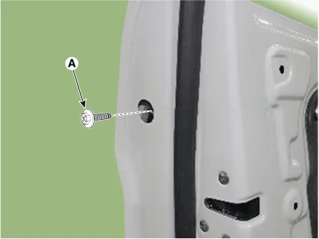
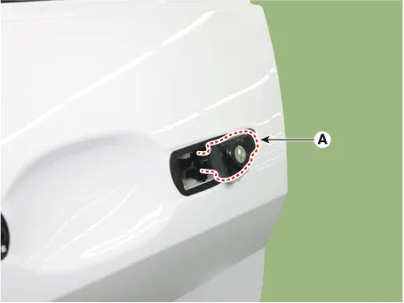
| 2. | Loosen the mounting bolt after remove the plug hall (A). And then push the outside handle in the direction of arrow as illustration below.
|
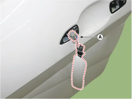
| 3. | Loosen the mounting screw (A) and then remove the front door outside handle (B) by sliding it forward.
|

| 4. | Remove the front door lock assembly (A).
|
| 5. | Disconnect the front door outside handle connector (A).
|
| 1. | Disconnect the negative (-) battery terminal. |
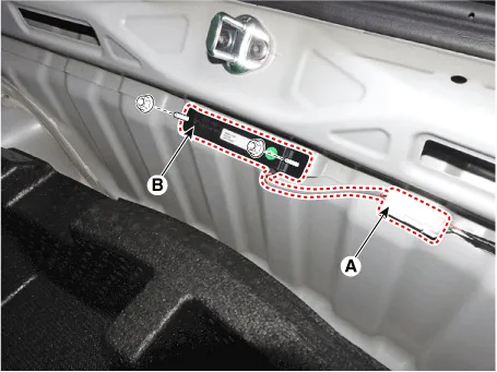
| 2. | Remove the inside rear combination lamp (A). (Refer to Lighting System - "Rear Combination Lmap") |
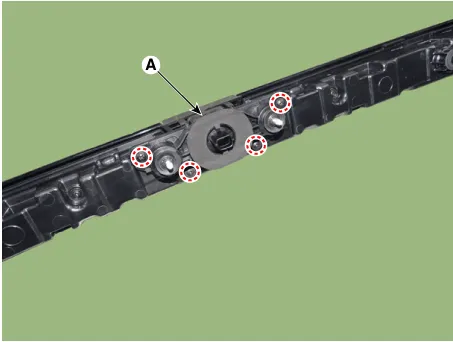
| 3. | Remove the trunk rid open switch assembly (A).
|
| Installation |
| 1. | Install the interior 1 antenna. |
| 2. | Install the floor console assembly. |
| 3. | Install the negative (-) battery terminal and check the smart key system. |
| 1. | Install the interior 2 antenna. |
| 2. | Install the console rear complete assembly. |
| 3. | Install the negative (-) battery terminal and check the smart key system. |
| 1. | Install the interior 3 antenna. |
| 2. | Install the rear transverse trim. |
| 3. | Install the negative (-) battery terminal and check the smart key system. |
| 1. | Install the exterior bumper antenna. |
| 2. | Install the rear bumper cover. |
| 3. | Install the negative (-) battery terminal and check the smart key system. |
| 1. | Install the exterior bumper antenna. |
| 2. | Install the front bumper cover. |
| 3. | Install the negative (-) battery terminal and check the smart key system. |
| 1. | Install the front door antenna. |
| 2. | Install the front door trim. |
| 3. | Install the negative (-) battery terminal and check the smart key system. |
| 1. | Install the buzzer. |
| 2. | Install the front left wheel guard. |
| 3. | Install the negative (-) battery terminal and check the smart key system. |
| 1. | Install the outside handle. |
| 2. | Install the door trim. |
| 3. | Install the negative (-) battery terminal and check the smart key system. |
| 1. | Install the Trunk rid open switch. |
| 2. | Install the inside rear combination lamp. |
| 3. | Install the negative (-) battery terminal and check the smart key system. |
Repair procedures InspectionSelf Diagnosis With Scan ToolIt will be able to diagnose defects of SMART KEY system with Diagnostic tool quickly. Diagnostic tool can operates actuator forcefully, input/output value monitoring and self diagnosis.
Other information:
Hyundai Elantra (CN7) 2021-2026 Service Manual: Description and operating principle
Description and OperationWireless Power Charger SystemDuring ACC or IG ON, battery voltage is supplied to the wireless power charger system to transmit an output of 5 W to mobile phone. Mobile phones certified with the wireless charging standard WPC (Qi 1.
Hyundai Elantra (CN7) 2021-2026 Service Manual: Intake Actuator
Description and operation DescriptionThe intake actuator is located at the blower unit. It regulates the intake door by a signal from the control unit. Pressing the intake selection switch will shift between recirculation and fresh air modes. Components and components location Components Location1.
Categories
- Manuals Home
- Hyundai Elantra Owners Manual
- Hyundai Elantra Service Manual
- General Tightening Torque Table. General information
- Maintenance
- Suspension System
- New on site
- Most important about car
