Hyundai Elantra (CN7): Blower / Intake Actuator
Hyundai Elantra (CN7) 2021-2026 Service Manual / Heating, Ventilation and Air Conditioning / Blower / Intake Actuator
Description and operation
| Description |
The intake actuator is located at the blower unit. It regulates the intake door by a signal from the control unit. Pressing the intake selection switch will shift between recirculation and fresh air modes.
Components and components location
| Components Location |
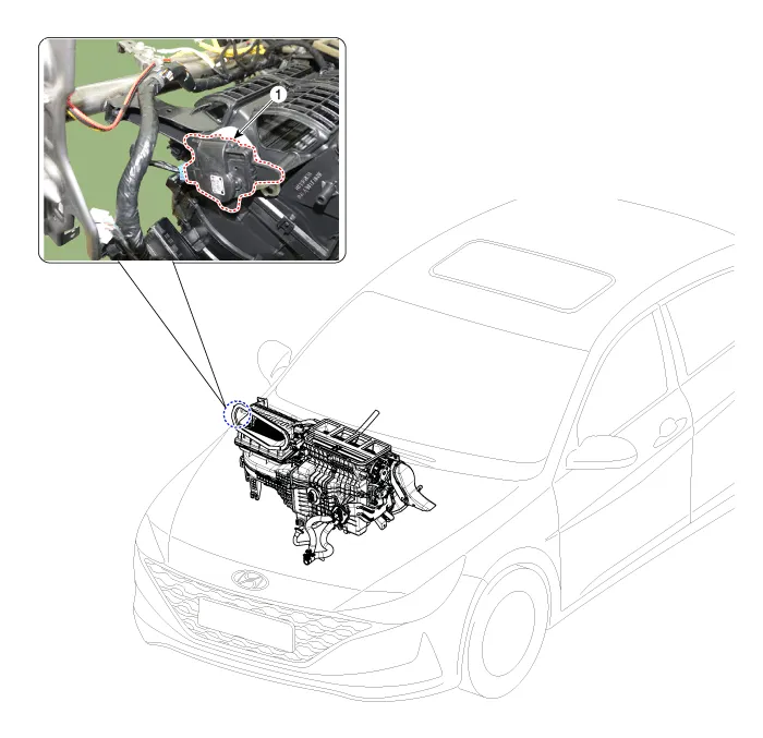
| 1. Intake actuator |
Specifications
| Specifications |
|
Door position
|
Voltage (V)
|
Error detecting
|
| Max. cooling | 0.3 ± 0.15 | Low voltage : 0.1V or less |
| Max. heating | 4.7 ± 0.15 | High voltage : 4.9V or more |
Repair procedures
| Inspection |
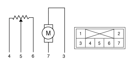
| 1. | Verify that the intake actuator operates to the fresh position when connecting 12V to terminal 3 and grounding terminal 7. |
| 2. | Verify that the intake actuator operates to the recirculation position when connected in reverse.
|
| 3. | Connect the intake actuator connector. |
| 4. | Turn the ignition switch ON. |
| 5. | Check the voltage between terminal 6 and 5. |
| 6. | If the measured voltage is not within specification, check the operation by replacing the existing intake actuator with a new genuine part. After that, determine whether replacement of the temperature control actuator is required or not. |
| Replacement |
| 1. | Disconnect the negative (-) battery terminal. |
| 2. | Remove the Heater & Blower unit assebmly. (Refer to Heater - "Heater Unit") |
| 3. | Disconnect the connector (A) and then remove the intake actuator (B) after loosening the mounting screws.
|
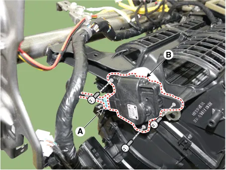
| 4. | To install, reverse the removal procedure. |
Description and operation Description The climate control air filter is located in the blower unit. It eliminates foreign materials and odor. The particle filter performs a role as an odor filter as well as a conventional dust filter to ensure comfortable interior environment.
Other information:
Hyundai Elantra (CN7) 2021-2026 Service Manual: Components and components location
C
Hyundai Elantra (CN7) 2021-2026 Service Manual: Description and operating principle
Description and OperationWireless Power Charger SystemDuring ACC or IG ON, battery voltage is supplied to the wireless power charger system to transmit an output of 5 W to mobile phone. Mobile phones certified with the wireless charging standard WPC (Qi 1.
Categories
- Manuals Home
- Hyundai Elantra Owners Manual
- Hyundai Elantra Service Manual
- Vehicle Information
- Engine Mechanical System
- Engine Control / Fuel System
- New on site
- Most important about car

Copyright © 2026 www.helantra7.com - 0.0201