Hyundai Elantra (CN7): SRSCM / SRS Control Module (SRSCM)
Description and operation
| Description |
| • | Supplemental Restraint System Control Module (SRSCM) determines whether and when to deploy air bag module, seat belt pretensioner (BPT). |
| • | It supplies the air bag module with the power required to deploy the module or the BPT. |
| • | It also performs self-diagnosis function of the supplemental restraint system. |
Components and components location
| Components |
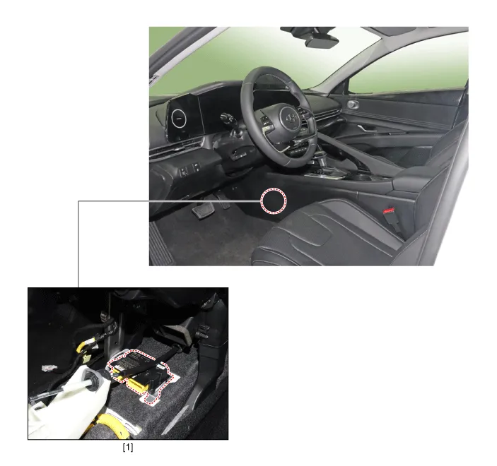
| 1. Supplemental Restraint System Control Module (SRSCM) |
Supplemental Restraint System Control Module (SRSCM)
|
No
|
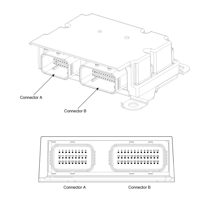
Connector A
|
Connector B
|
| 1 | IGN 1 | Ground |
| 2 | Driver front impact sensor - High (+) | Driver seat belt pretensioner - High (+) |
| 3 | Driver front impact sensor - Low (-) | Driver seat belt pretensioner - Low (-) |
| 4 | Driver airbag 1st stage - High (+) | Driver adapted road limiter - High (+) |
| 5 | Driver airbag 1st stage - Low (-) | Driver adapted road limiter - Low (-) |
| 6 | Passenger airbag 1st stage - Low (-) | Driver side airbag - High (+) |
| 7 | Passenger airbag 1st stage - High (+) | Driver side airbag - Low (-) |
| 8 | - | Passenger side airbag - Low (-) |
| 9 | - | Passenger side airbag - High (+) |
| 10 | Crash signal output | Driver side impact sensor - High (+) |
| 11 | Passenger front impact sensor - High (+) | Driver side impact sensor - Low (-) |
| 12 | Passenger front impact sensor - Low (-) | Passenger side impact sensor - Low (-) |
| 13 | Driver airbag 2nd stage - High (+) | Passenger side impact sensor - High (+) |
| 14 | Driver airbag 2nd stage - Low (-) | Passenger seat belt buckle sensor - High (+) |
| 15 | Passenger airbag 2nd stage - Low (-) | Passenger seat belt pretensioner - High (+) |
| 16 | Passenger airbag 2nd stage - High (+) | Passenger seat belt pretensioner - Low (-) |
| 17 | C-CAN (High) | - |
| 18 | C-CAN (Low) | - |
| 19 | B + | Driver curtain airbag - High (+) |
| 20 | Passenger airbag OFF lamp | Driver curtain airbag - Low (-) |
| 21 | - | Passenger curtain airbag - Low (-) |
| 22 | - | Passenger curtain airbag - High (+) |
| 23 | - | Driver Passenger side impact sensor - High (+) |
| 24 | - | Driver pressure side impact sensor - Low (-) |
| 25 | - | Passenger pressure side impact sensor - Low (-) |
| 26 | Local CAN (High) | Passenger Passenger side impact sensor - High (+) |
| 27 | Local CAN (Low) | Driver seat belt buckle sensor - High (+) |
| 28 | Driver rear seat belt pretensioner - High (+) | |
| 29 | Driver rear seat belt pretensioner - Low (-) | |
| 30 | Passenger rear seat belt pretensioner - High (+) | |
| 31 | Passenger rear seat belt pretensioner - Low (-) | |
| 32 | - | |
| 33 | - | |
| 34 | - | |
| 35 | - | |
| 36 | - | |
| 37 | - | |
| 38 | - | |
| 39 | - |
Repair procedures
| Removal |
| 1. | Turn the ignition switch OFF and disconnect the battery negative (-) cable.
|

| 2. | Remove the floor console assembly. (Refer to Body - "Floor Console Assembly") |
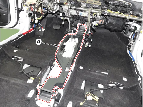
| 3. | Remove the center console duct (A).
|
| 4. | Pull up the lock of the SRSCM connector to disconnect the connector (A).
|

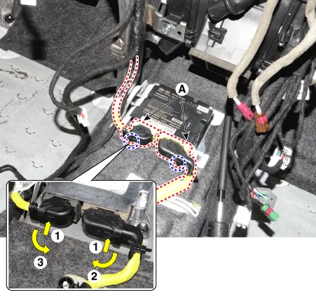
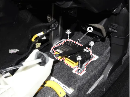
| 5. | Remove the SRSCM (A) after loosening the mounting nuts.
|
| Installation |
| 1. | Check if the battery (-) cable is disconnected.
|
| 2. | Install the SRSCM (A) with the SRSCM mounting nuts.
|
| 3. | Connect the SRSCM harness connector. |
| 4. | Install the heater ducts and floor console. (Refer to Body - "Floor Console Assembly") |
| 5. | Reconnect the battery negative cable. |
| 6. | After installing the SRSCM, confirm proper system operation :
|
| Adjustment |
[Variant Coding]
| 1. | Connect the cable of diagnostic tool to the data link connector in driver side crash pad lower panel, and turn on the diagnostic tool. |
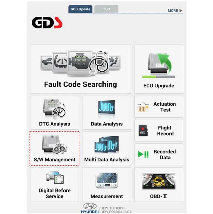
| 2. | Select the 'S/W Management' and 'Car model'.
|
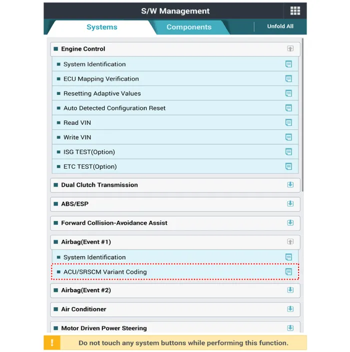
| 3. | Select "Airbag" and "ACU/SRSCM Variant Coding".
|
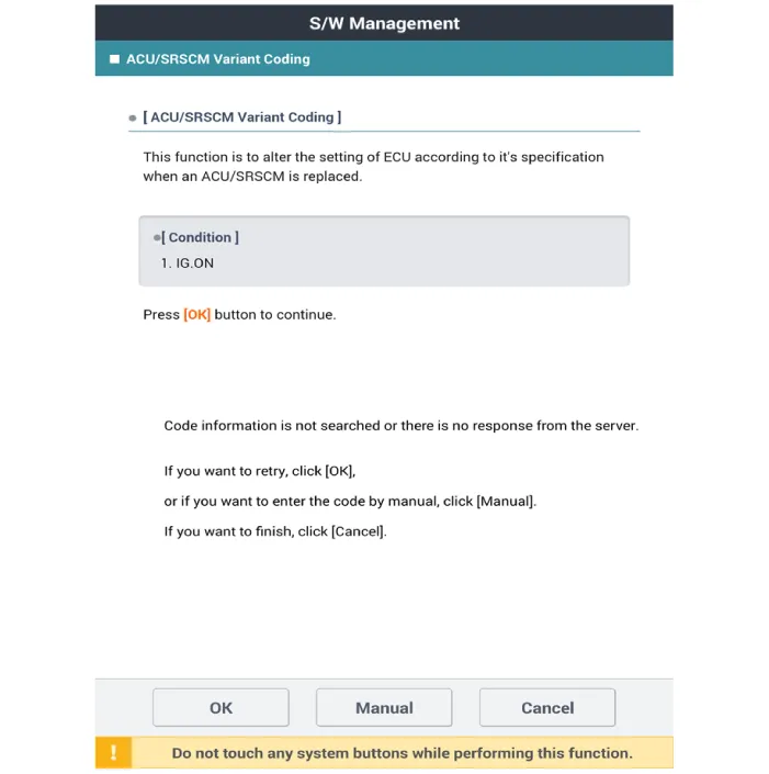
| 4. | Perform the "ACU/SRSCM Variant Coding" procedure according to the GDS screen message.
|
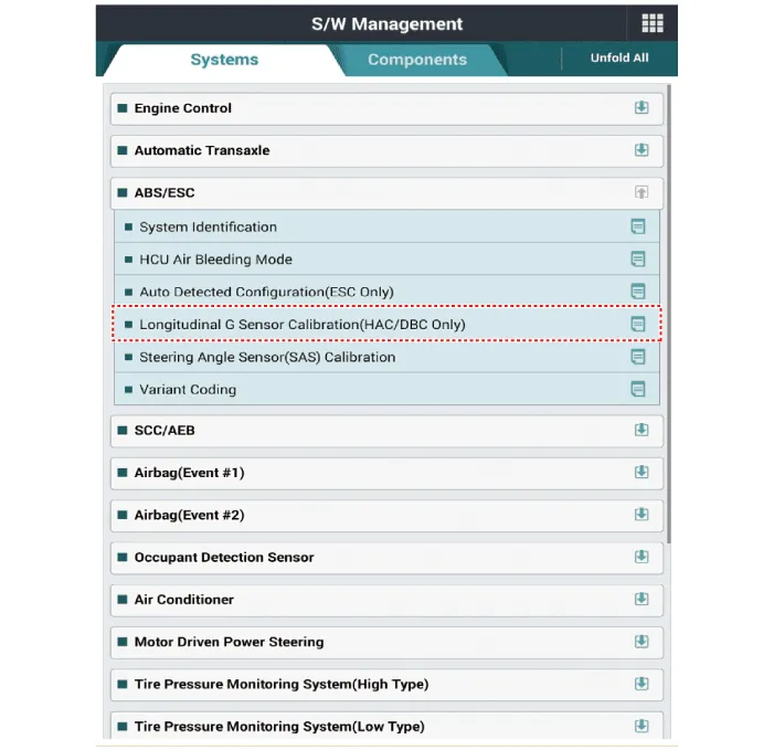
[Longitudinal G Sensor Calibration]
| 1. | Connect the cable of diagnostic tool to the data link connector in driver side crash pad lower panel, and turn on the diagnostic tool. |
| 2. | Select the 'S/W Management' and 'Car model'.
|
| 3. | Select "Longitudinal G Sensor Calibration".
|
Components1. Front impact sensor (FIS)2. Supplemental Restraint System Control Module (SRSCM)3. Front impact sensor (FIS)4. Gravity side Impact Sensor (G-SIS)5.
Description and operation DescriptionThe front impact sensor (FIS) is installed in the Front End Module (FEM). They are remote sensors that detect acceleration due to a collision at its mounting location.
Categories
- Manuals Home
- Hyundai Elantra Owners Manual
- Hyundai Elantra Service Manual
- Specifications
- Repair procedures
- Body (Interior and Exterior)
- New on site
- Most important about car

Copyright © 2026 www.helantra7.com - 0.0193