Hyundai Elantra (CN7): Body Electrical System / Sun Roof
Components and components location
| Component Location |
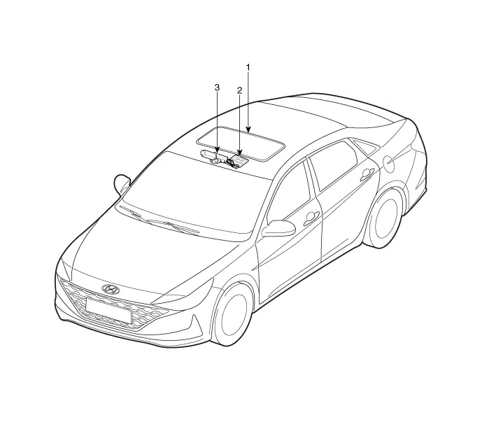
| 1. Sunroof 2. Sunroof switch | 3. Sunroof motor & controller |
Schematic diagrams
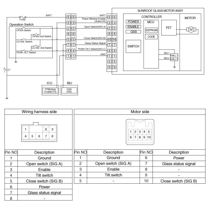
| Circuit Diagram |
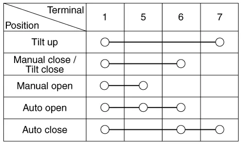
Sunroof Switch
Repair procedures
| Inspection |
| 1. | Disconnect the negative (-) battery terminal. |
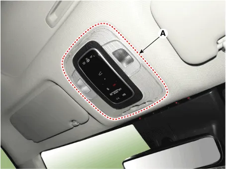
| 2. | Using a remover and remove the overhead console (A).
|
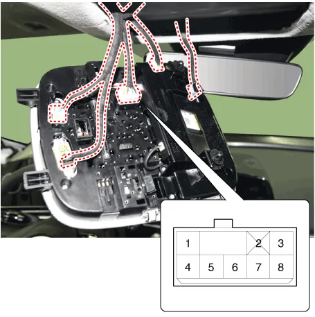
| 3. | Check for continuity between the terminals.
|
Sunroof Motor
Repair procedures
| Inspection |
| 1. | Disconnect the negative (-) battery terminal. |
| 2. | Remove the roof trim. (Refer to Body - "Roof Trim") |
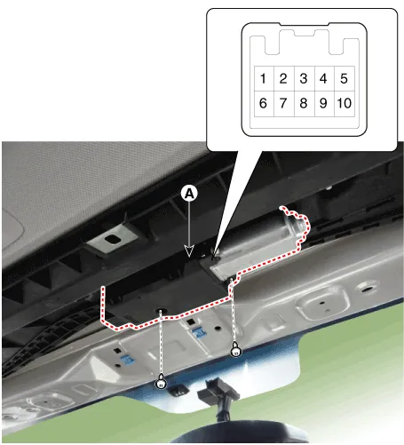
| 3. | Disconnect the sunroof motor (A) connector.
|
| 4. | Ground the terminals as below table, and check that the sunroof unit operates.
|

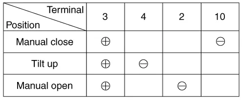
| 5. | Make these input tests at the connector. If any test indicates a problem, find and correct the cause, then recheck the system. If all the input tests prove OK, the sunroof motor must be faulty; replace it.
|
| Resetting the Sunroof |
| 1. | Turn the ignition key to the ON position and then close the sunroof completely. |
| 2. | Release the sunroof control lever. |
| 3. | Press and hold the CLOSE button for more than 10 seconds until the sunroof closed and it has moved slightly. |
| 4. | Release the sunroof control lever. |
| 5. | Press and hold the CLOSE button once again within 5 seconds until the sunroof do as follows;
|
| 6. | Reset procedure of panorama system is finished. |
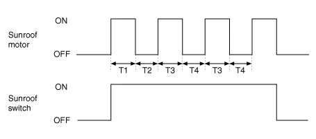
| 1. | The sunroof ECU detects the Run- time of motor |
| 2. | Motor can be operated continuously for the 1st run-time (120 ± 10sec.). |
| 3. | The continuous operation of motor stops after the 1st Run-time (120 ± 10sec.). |
| 4. | Then Motor is not operated for the 1st Cool-time (18 ± 2sec.). |
| 5. | Motor is operated for the 2nd Run-time (10 ± 2sec.) at the continued motor operation after 1st Cool-time (18 ± 2sec.) |
| 6. | The continuous operation of motor stops operating after the 2nd Run-time (10 ± 2sec.) |
| 7. | Motor is not operated for the 2nd Cool-time (18 ± 2sec.). |
| 8. | Motor repeats the 2nd run-time and 2nd cool-time at the continued motor operation.
T1 : 120 ± 10 sec., T2 : 18 ± 2 sec., T3 : 10 ± 2 sec., T4 : 18 ± 2 sec. |
Description and operation DescriptionThe ECM (Electro Chromatic inside rear view Mirror) is intended dim the reflecting light in the rear view mirror.
Other information:
Hyundai Elantra (CN7) 2021-2026 Service Manual: Description and operation
DescriptionSystem OverviewThe System offers the following features:– Human / machine interface through a 1-stage button, for terminal switching and engine start.– Control of external relays for ACC / IGN1 / IGN2 terminal switching and STARTER, without use of mechanical ignition switch.
Hyundai Elantra (CN7) 2021-2026 Service Manual: Troubleshooting
TroubleshootingProblem Symptoms TableBefore replacing or repairing air conditioning components, first determine if the malfunction is due to the refrigerant charge, air flow or compressor.Use the table below to help you find the cause of the problem. The numbers indicate the priority of the likely cause of the problem.
Categories
- Manuals Home
- Hyundai Elantra Owners Manual
- Hyundai Elantra Service Manual
- Troubleshooting
- Engine Control / Fuel System
- Integrated Thermal Management Module (ITM)
- New on site
- Most important about car
