
Hyundai Elantra (CN7): Body Electrical System / Electro Chromic Inside Rear View Mirror
Description and operation
| Description |
| 1. | The forward facing sensor sees if the brightness of the surroundings is low enough for the mirror to operate its function. |
| 2. | The rearward looking sensor detects glaring of the reflecting light from a vehicle behind. |
| 3. | The ECM is darkened to the level as determined by the rearward looking sensor. When the glaring is no longer detected, the mirror stops functioning.
|

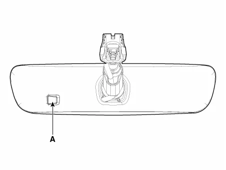
| Automatic-dimming Function |
| 1. | Pressing and holding the Feature Control button for more than 3 but less than 6 seconds turns the auto-dimming function OFF which is indicated by the green Status Indicator LED turning off. |
| 2. | Pressing and holding the Feature Control button again for more than 3 but less than 6 seconds turns the auto-dimming function ON which is indicated by the green Status Indicator LED turning on.
|

Components and components location
| Components (1) |
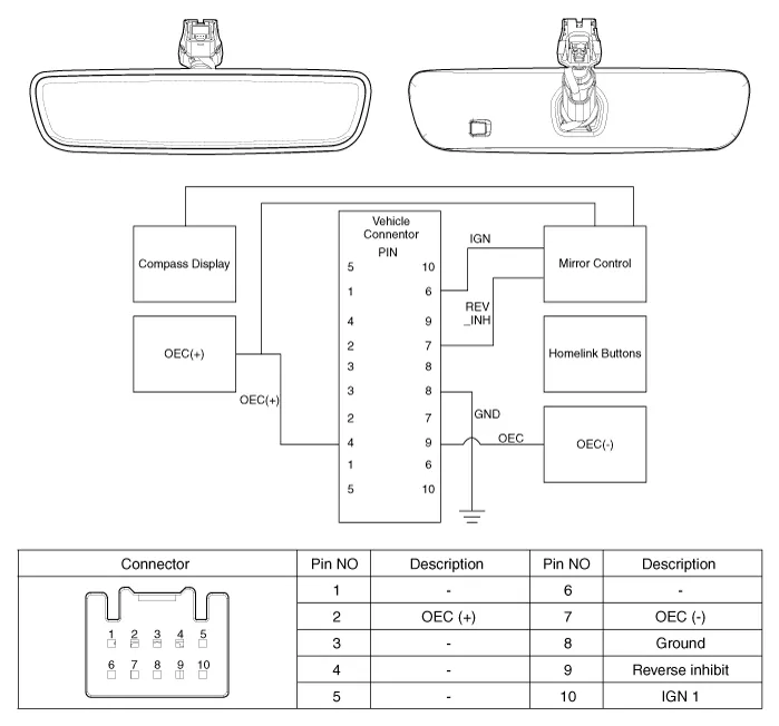
Repair procedures
| Inspection |
| 1. | Turn the ignition key to the "ON" position. |
| 2. | Cover the forward facing sensor. |
| 3. | Head a light to the rearward looking sensor. |
| 4. | The ECM should be darkened as soon as the rearward looking sensor detects the light.
|
| 5. | When the reverse gear is engaged, the ECM should not be darkened. When heading lights to both the forward facing and rearward looking sensors, the ECM should not be darkened. |
| Removal |
| 1. | Remove the inside rear view mirror cover (A).
|
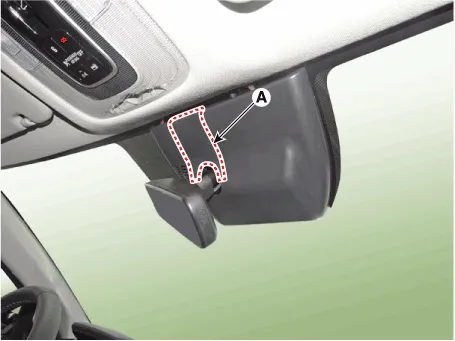
| 2. | Using a remover and remove the rain sensor cover (A).
|

| 3. | Disconnect the inside rear view mirror connector (A).
|
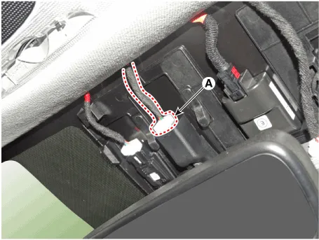
| 4. | Loosen the mounting screw and remove the inside rear view mirror (A).
|
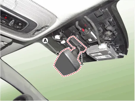
| Installation |
| 1. | Install the mirror making sure the mounting bracket not to be damaged. |
| 2. | Install the mirror wiring cover and rain sensor cover after reconnecting the connector and tightening the screw. |
Description and operation DescriptionIntegrated Rain SensorIntegrated rain sensor (A) controls three systems: front wiper, auto-light, and central air conditioner.
Components and components location Component Location1. Sunroof2. Sunroof switch3. Sunroof motor & controller Schematic diagrams Circuit Diagram Sunroof Switch Repair procedures Inspection1.
Other information:
Hyundai Elantra (CN7) 2021-2026 Service Manual: Smart Cruise Control (SCC) Switch
Schematic diagrams Circuit DiagramTRIP / SCC / LFA Repair procedures Inspection1.Check for resistance between terminals in each switch position (LH).[LH : Audio + Hands free] Switch Resistance (±5%) SEEK Up430 ΩSEEK Down1.
Hyundai Elantra (CN7) 2021-2026 Service Manual: Description and operation
DescriptionThe cruise control system is engaged by the cruise "ON/OFF" main switch located on right of steering wheel column. The system has the capability to cruise, coast, accelerate and resume speed.It also has a safety interrupt, engaged upon depressing brake or shifting select lever.
Categories
- Manuals Home
- Hyundai Elantra Owners Manual
- Hyundai Elantra Service Manual
- Driver assistance system
- Rear Seats
- General Tightening Torque Table. General information
- New on site
- Most important about car
