Hyundai Elantra (CN7): Fuses And Relays / Components and components location
Hyundai Elantra (CN7) 2021-2026 Service Manual / Body Electrical System / Fuses And Relays / Components and components location
| Component Location |
[Engine Room]
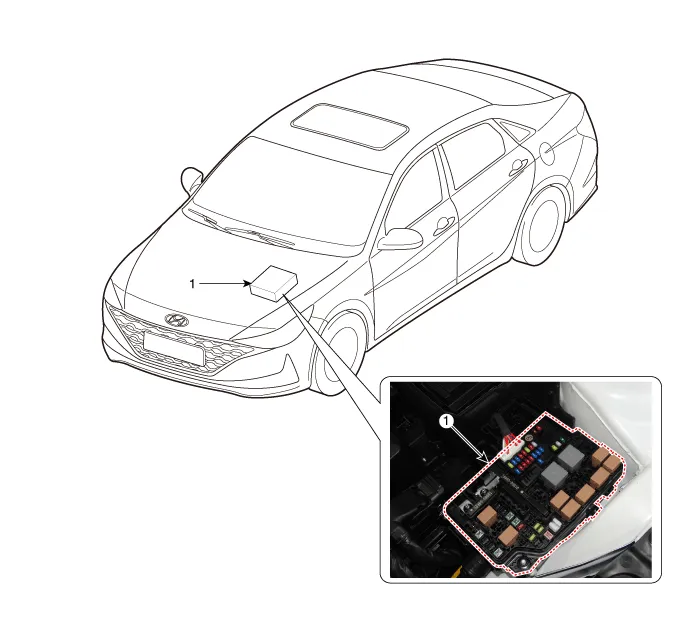
| 1. Engine room junction block |
[Interior Relay]
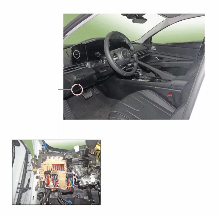
| 1. ICU (Integrated Central Control Unit) |
Repair procedures Inspection1.Disconnect the negative (-) battery terminal.2.Pull out the relay from the engine compartment relay block.Power Relay (Type A) Check for continuity between the terminals.
Other information:
Hyundai Elantra (CN7) 2021-2026 Service Manual: Special service tools
S
Hyundai Elantra (CN7) 2021-2026 Service Manual: Blower Unit
Components and components location Component Location1. Blower unit assemblyComponents1. Blower unit assebmly2. Blower upper cover [LH]3. Duct seal4. Blower upper cover [RH]5. Intake actuator6. Air filter cover7. Intake door8. Air filter9. Blower upper case10.
Categories
- Manuals Home
- Hyundai Elantra Owners Manual
- Hyundai Elantra Service Manual
- Vehicle Information
- Rear Seats
- Drive Mode
- New on site
- Most important about car

Copyright © 2026 www.helantra7.com - 0.0151