
Hyundai Elantra (CN7): Manual Transaxle Control System / Control Shaft Complete
Hyundai Elantra (CN7) 2021-2026 Service Manual / Manual Transaxle System / Manual Transaxle Control System / Control Shaft Complete
Description and operation
| Description |
Component location
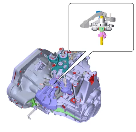
Operation principle : Control shaft assembly is operated by shifting the shift lever.
Repair procedures
| Removal |
| 1. | Set shift lever to N position. |
| 2. | Remove the air cleaner assembly and air duct. (Refer to Engine Mechnical System - "Air Cleaner") |
| 3. | Remove the battery and battery tray. (Refer to Engine Electrical System - "Battery") |
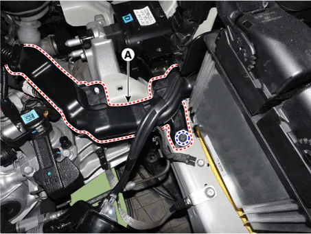
| 4. | Loosen the bolt and then separate the engine wiring (A).
|
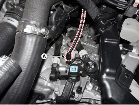
| 5. | Disconnect the back-up lamp switch connector (A).
|
| 6. | Remove the snap pin (A) and then separate the shift cable (B) and the select cable (C) from the control shaft complete.
|

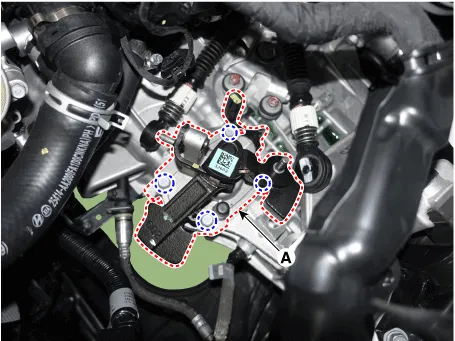
| 7. | Remove the control shaft assembly (A) after loosening the bolts.
|
| Installation |
| 1. | To install, reverse the removal procedures. |
|

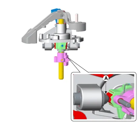
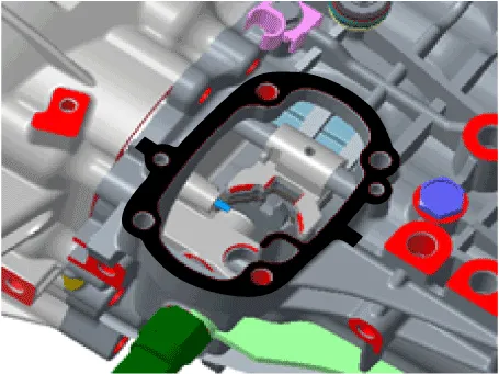
|

Components and components location Components1. Shift lever knob & boots2. Shift lever assembly3. Select cable4. Shift cable5. Retainer Repair procedures Removal1.
Other information:
Hyundai Elantra (CN7) 2021-2026 Service Manual: Specification
S
Hyundai Elantra (CN7) 2021-2026 Service Manual: Temperature Control Actuator
Description and operation DescriptionThe temperature control actuator is located at the heater unit. It regulates the temperature by the procedure as follows. The signal from the control unit adjusts the position of the temperature door by operating the temperature switch.
Categories
- Manuals Home
- Hyundai Elantra Owners Manual
- Hyundai Elantra Service Manual
- Drive Mode
- Engine Mechanical System
- Front Bumper
- New on site
- Most important about car

Copyright © 2026 www.helantra7.com - 0.012