Hyundai Elantra (CN7): Front Suspension System / Front Lower Arm
Repair procedures
| Removal |
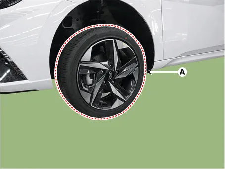
| 1. | Loosen the wheel nuts slightly. Raise the vehicle, and make sure it is securely supported. |
| 2. | Remove the front wheel and tire (A) from the front hub.
|

| 3. | Remove the engine room under cover. (Refer to Engine Mechanical System - "Engine Room Under Cover") |
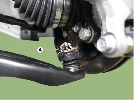
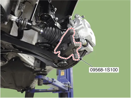
| 4. | Loosen the lower arm nut (A) and then remove the lower arm ball joint by using SST(09568-1S100).
|
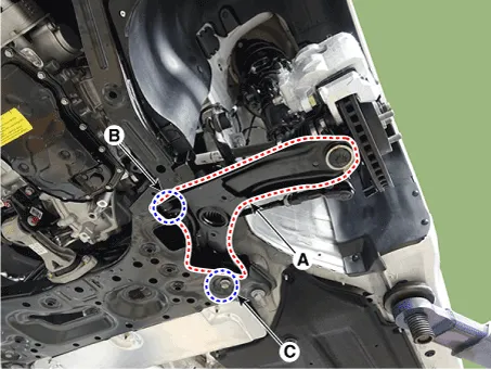
| 5. | Remove the front lower arm (A) after loosening the mounting bolts.
|
| Inspection |
| 1. | Check the bushing for wear and deterioration. |
| 2. | Check the lower arm for bending or breakage. |
| 3. | Check the ball joint dust cover for crack. |
| 4. | Check the all bolts and nuts. |
| Installation |
| 1. | To install, reverse the removal procedures. |
| 2. | Check the alignment. (Refer to Suspension System - "Alingment") |
Components and components location Components 1. Insulator cap2. Lock nut3. Insulator & sturt bearing4. Bumper rubber5. Dust cover6. Coil spring7.
Repair procedures Removal1.Loosen the wheel nuts slightly.Raise the vehicle, and make sure it is securely supported.2.Remove the front wheel and tire (A) from the front hub.
Other information:
Hyundai Elantra (CN7) 2021-2026 Service Manual: Warning Indicator
Components and components location Components1. BSD Indicator2. Side repeater lamp Repair procedures Inspection1.Disconnect the negative (-) battery terminal.2.Remove the front door trim.(Refer to Body - "Front door trim")3.Disconnect the power door mirror connector from the harness4.
Hyundai Elantra (CN7) 2021-2026 Service Manual: ADAS Parking ECU (ADAS_PRK)
Components and components location Components and Components Location Repair procedures Removal • Use a plastic panel removal tool to remove interior trim pieces without marring the surface.• Take care not to bend or scratch the trim and panels.
Categories
- Manuals Home
- Hyundai Elantra Owners Manual
- Hyundai Elantra Service Manual
- General Tightening Torque Table. General information
- Instrument Panel Overview
- Drive Mode
- New on site
- Most important about car
