Hyundai Elantra (CN7): Front Suspension System / Front Stabilizer Bar
Repair procedures
| Removal |
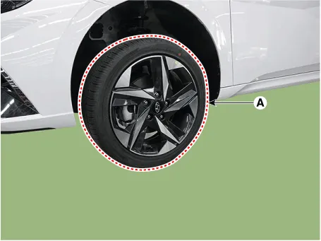
| 1. | Loosen the wheel nuts slightly. Raise the vehicle, and make sure it is securely supported. |
| 2. | Remove the front wheel and tire (A) from the front hub.
|

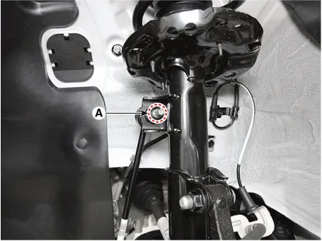
| 3. | Remove stabilizer bar link from the front strut after loosening the mounting nut.
|
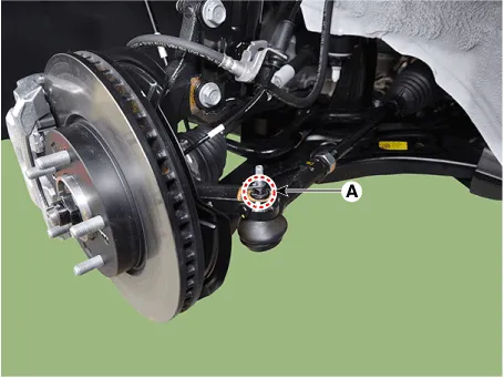
| 4. | Remove the tie rod end ball joint by using the special service tool.
|
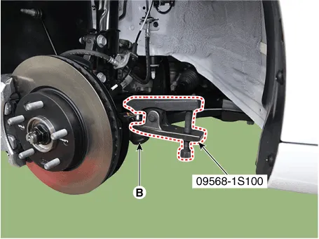
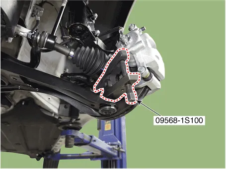
| 5. | Separate the lower arm ball joint by using the SST (09568-1S100) after loosening the lower arm mounting nut (A).
|
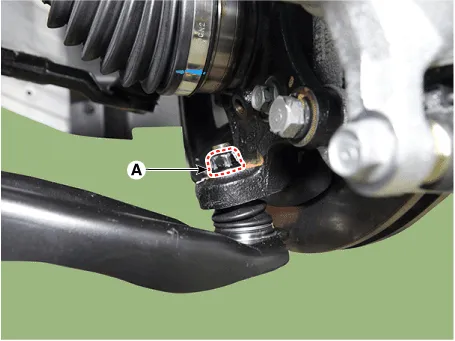
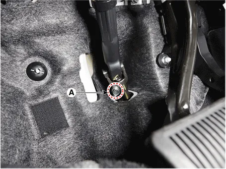
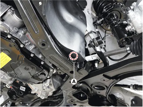
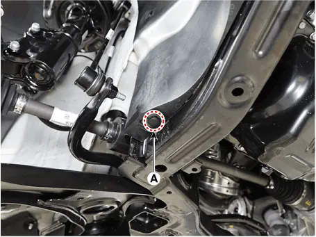
| 6. | Separate the universal joint from the steering gear box after loosening the universal joint mounting bolt (A).
|

| 7. | Remove the engine room under cover. (Refer to Engine Mechanical System - "Engine Room Under Cover") |
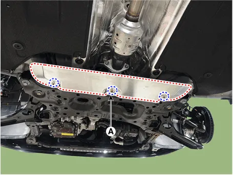
| 8. | Remove the heat protector (A).
|
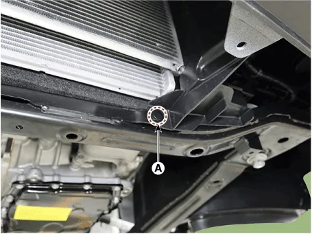
| 9. | Remove the muffler rubber hanger (A).
|
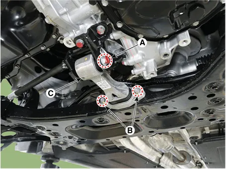
| 10. | Remove the roll rod bracket (C) after loosening the mounting bolts (A, B).
|
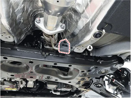
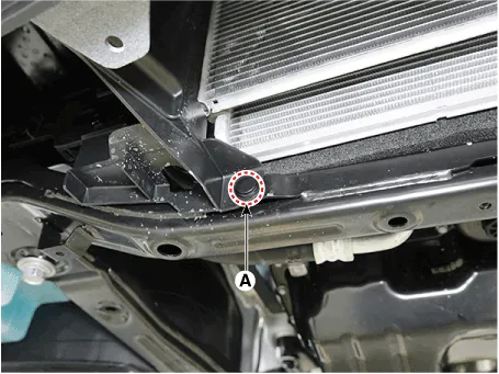
| 11. | Remove the fastener (A). [LH]
[RH]
|
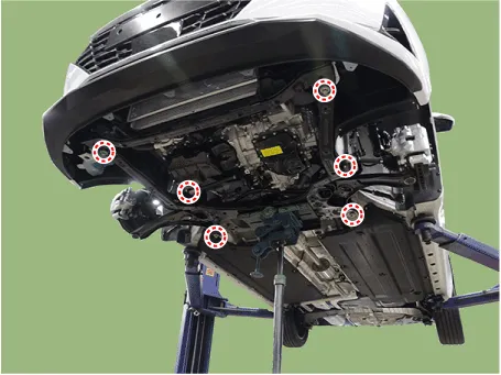
| 12. | Remove the sub frame after loosening the mounting bolts and nuts.
|

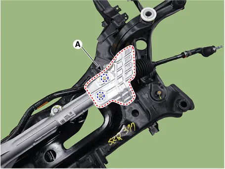
| 13. | Remove the heat protector (A).
|

| 14. | Remove the steering gear box (A) from the sub frame after loosening the mounting bolts.
|
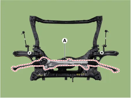
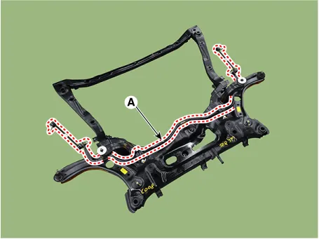
| 15. | Remove the stabilizer bar (A) from the sub frame after loosening the mounting bolts.
|
| 16. | Remove the stabilizer bar link from the stabilizer bar after loosening the mounting nuts.
|

| 17. | Remove the stabilizer bar bushing.
|

| Installation |
| 1. | To install, reverse the removal procedures. |
| 2. | Check the alignment. (Refer to Suspension System - "Alingment") |
Repair procedures Removal1.Loosen the wheel nuts slightly.Raise the vehicle, and make sure it is securely supported.2.Remove the front wheel and tire (A) from the front hub.
Repair procedures Removal[A type]1.Loosen the wheel nuts slightly.Raise the vehicle, and make sure it is securely supported.2.Remove the front wheel and tire (A) from the front hub.
Other information:
Hyundai Elantra (CN7) 2021-2026 Service Manual: Refrigerant Line
Components and components location Components Location1. Refrigerant Pipe Assembly Repair procedures Replacement1.If the compressor is marginally operable, run the engine at idle speed, and let the air conditioning work for a few minutes, then shut the engine off.
Hyundai Elantra (CN7) 2021-2026 Service Manual: Heater Core
Repair procedures Replacement1.Disconnect the negative (-) battery terminal. 2.Remove the heater and blower assembly.(Refer to Heater - "Heater Unit") 3.Remove the heater core cover (A) after loosening the mounting screws.4.Pull out the heater core (A) from the heater unit.
Categories
- Manuals Home
- Hyundai Elantra Owners Manual
- Hyundai Elantra Service Manual
- Driver assistance system
- Troubleshooting
- Suspension System
- New on site
- Most important about car
