Hyundai Elantra (CN7): Front Suspension System / Sub Frame
Repair procedures
| Removal |
| 1. | Loosen the wheel nuts slightly. Raise the vehicle, and make sure it is securely supported. |
| 2. | Remove the front wheel and tire (A) from the front hub.
|


| 3. | Remove stabilizer bar link from the front strut after loosening the mounting nut.
|
| 4. | Remove the tie rod end ball joint by using the special service tool.
|
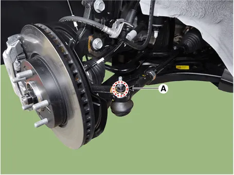
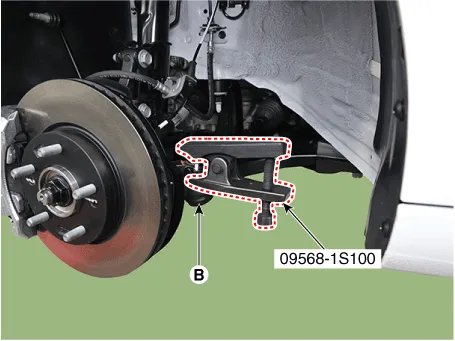
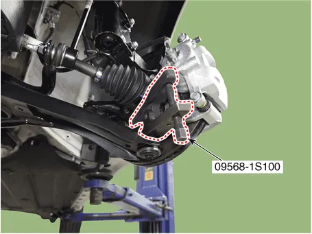
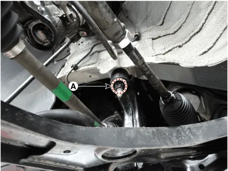
| 5. | Separate the lower arm ball joint by using the SST (09568-1S100) after loosening the lower arm mounting nut (A).
|
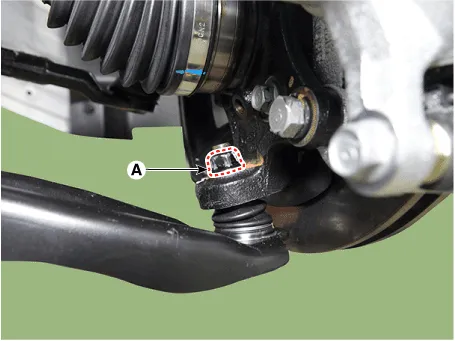
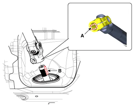
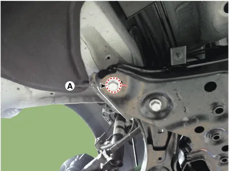
| 6. | Separate the universal joint from the steering gear box after loosening the universal joint mounting bolt (A).
|
| 7. | Remove the engine room under cover. (Refer to Engine Mechanical System - "Engine Room Under Cover") |
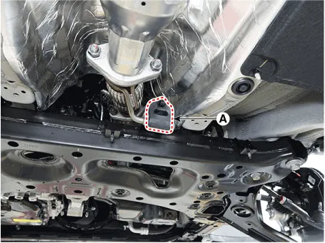
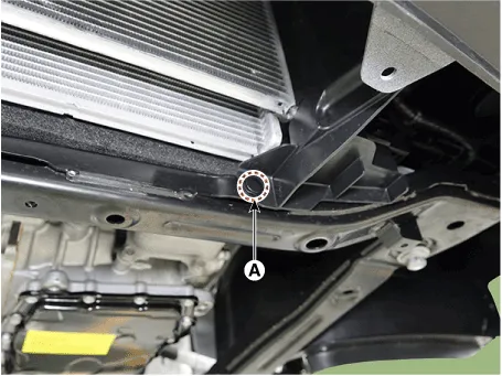
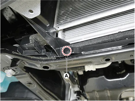
| 8. | Remove the muffler rubber hanger (A).
|
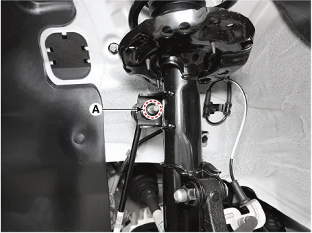
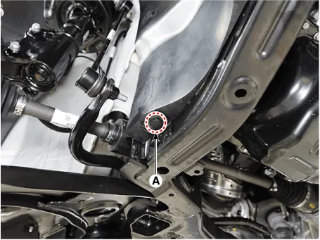
| 9. | Remove the roll rod bracket (C) after loosening the mounting bolts (A, B).
|
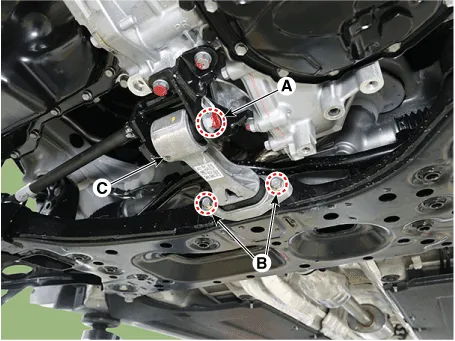
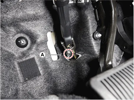
| 10. | Remove the fastener (A). [LH]
[RH]
|
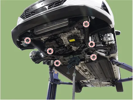
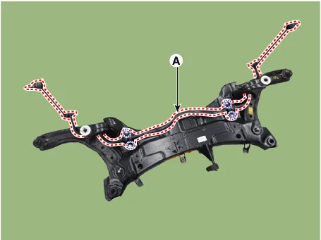
| 11. | Remove the sub frame after loosening the mounting bolts and nuts.
|

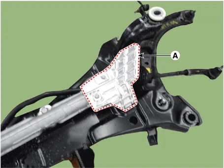
| 12. | Remove the heat protector (A).
|
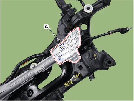
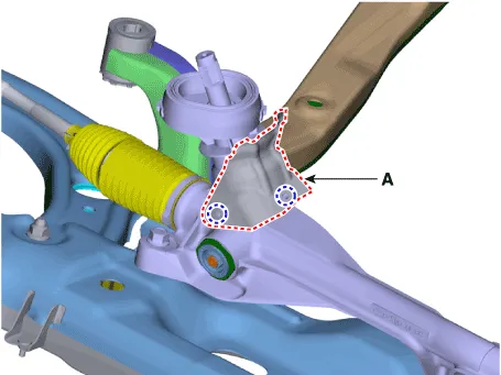
| 13. | Remove the steering gear box (A) from the sub frame after loosening the mounting bolts.
|
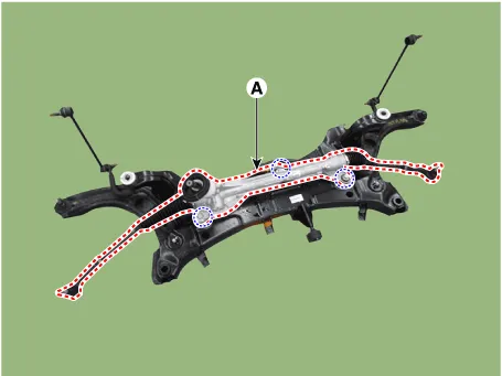
| 14. | Remove the stabilizer bar (A) from the sub frame after loosening the mounting bolts.
|
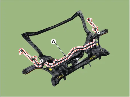
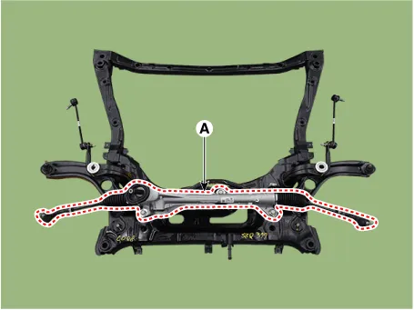
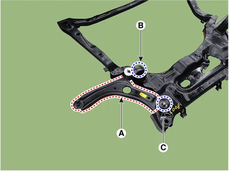
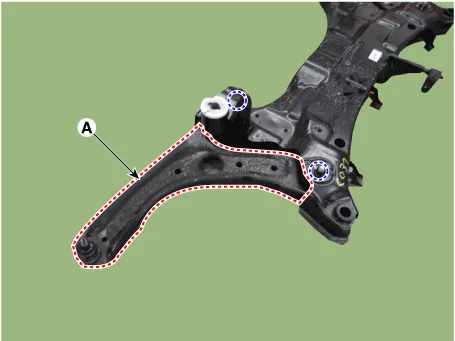
| 15. | Remove the front lower arm (A) from the sub frame.
[LH]
[RH]
|
| 1. | Loosen the wheel nuts slightly. Raise the vehicle, and make sure it is securely supported. |
| 2. | Remove the front wheel and tire (A) from the front hub.
|
| 3. | Remove stabilizer bar link from the front strut after loosening the mounting nut.
|
| 4. | Remove the tie rod end ball joint by using the special service tool.
|
| 5. | Separate the lower arm ball joint by using the SST (09568-1S100) after loosening the lower arm mounting nut (A).
|
| 6. | Separate the universal joint from the steering gear box after loosening the universal joint mounting bolt.
|
| 7. | Remove the engine room under cover. (Refer to Engine Mechanical System - "Engine Room Under Cover") |
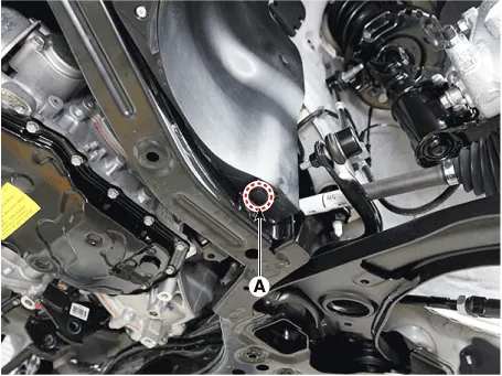
| 8. | Remove the muffler rubber hanger (A).
|
| 9. | Remove the roll rod bracket (C) after loosening the mounting bolts (A, B).
|
| 10. | Remove the subframe by loosening the mounting bolts (A) and nuts (B).
|
| 11. | Remove the heat protector (A).
|
| 12. | Remove the steering gear box (A) after loosening the mounting bolts.
|
| 13. | Remove the stabilizer bar (A) after loosening the mounting bolts.
|
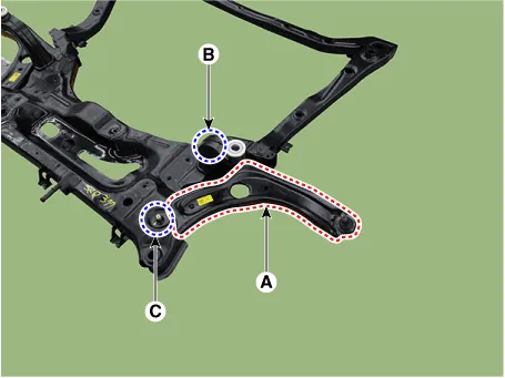
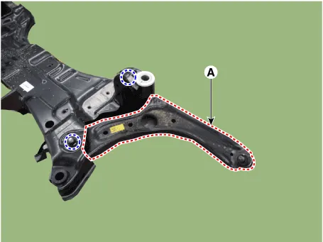
| 14. | Remove the front lower arm (A) from the sub frame.
[LH]
[RH]
|
| Installation |
| 1. | To install, reverse the removal procedures. |
| 2. | Check the alignment. (Refer to Suspension System - "Alingment") |
Repair procedures Removal1.Loosen the wheel nuts slightly.Raise the vehicle, and make sure it is securely supported.2.Remove the front wheel and tire (A) from the front hub.
Other information:
Hyundai Elantra (CN7) 2021-2026 Service Manual: Ignition Switch Assembly. Repair procedures
Repair procedures Replacement1.Disconnect the negative (-) battery terminal.2.Remove the crash pad lower panel.(Refer to Body - "Crash Pad")3.Remove the steering column upper & Lower shroud.4.Remove the ignition switch and disconnecting the Key Warning / immobilizer connector.
Hyundai Elantra (CN7) 2021-2026 Service Manual: Troubleshooting
Diagnosis with Diagnostic tool1.In the body electrical system, failure can be quickly diagnosed by using the vehicle diagnostic system (Diagnostic tool).The diagnostic system (Diagnostic tool) provides the following information.(1)Fault Code Searching : Checking failure and code number (DTC)(2)Data Analysis : Checking the system input/output data s
Categories
- Manuals Home
- Hyundai Elantra Owners Manual
- Hyundai Elantra Service Manual
- Auto Hold. Warning messages
- Front Bumper
- Rear Seats
- New on site
- Most important about car
