Hyundai Elantra (CN7): Front Suspension System / Front Lower Arm
Repair procedures
| Removal |
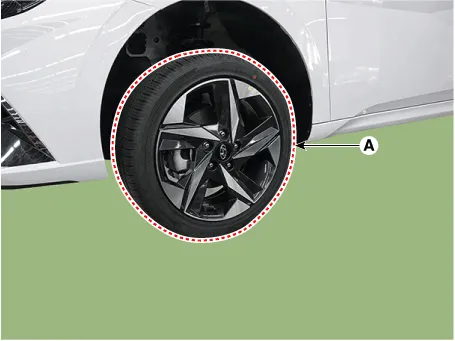
| 1. | Loosen the wheel nuts slightly. Raise the vehicle, and make sure it is securely supported. |
| 2. | Remove the front wheel and tire (A) from the front hub.
|

| 3. | Remove the engine room under cover. (Refer to Engine Mechanical System - "Engine Room Under Cover") |
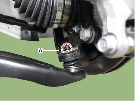
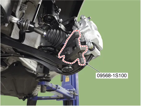
| 4. | Loosen the lower arm nut (A) and then remove the lower arm ball joint by using SST(09568-1S100).
|
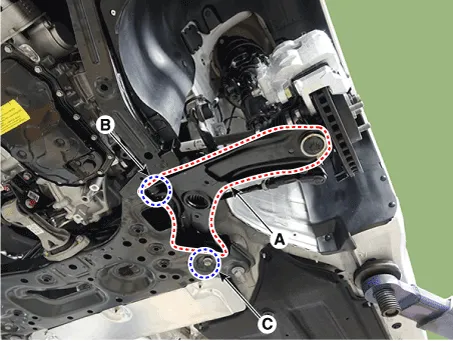
| 5. | Remove the front lower arm (A) after loosening the mounting bolts.
|
| Inspection |
| 1. | Check the bushing for wear and deterioration. |
| 2. | Check the lower arm for bending or breakage. |
| 3. | Check the ball joint dust cover for crack. |
| 4. | Check the all bolts and nuts. |
| Installation |
| 1. | To install, reverse the removal procedures. |
| 2. | Check the alignment. (Refer to Suspension System - "Alingment") |
Components and components location Components 1. Insulator cap2. Lock nut3. Insulator & sturt bearing4. Bumper rubber5. Dust cover6. Coil spring7.
Repair procedures Removal1.Loosen the wheel nuts slightly.Raise the vehicle, and make sure it is securely supported.2.Remove the front wheel and tire (A) from the front hub.
Other information:
Hyundai Elantra (CN7) 2021-2026 Service Manual: Description and operation
DescriptionSystem OverviewThe System offers the following features:– Human / machine interface through a 1-stage button, for terminal switching and engine start.– Control of external relays for ACC / IGN1 / IGN2 terminal switching and STARTER, without use of mechanical ignition switch.
Hyundai Elantra (CN7) 2021-2026 Service Manual: Specifications
SpecificationAir Conditioner Item Specification CompressorTypeGamma 1.6 MPI, Gasoline 2.0 NU MPI, Gasoline 1.6 T-GDI : 6HVx14Gasoline 1.6 MPI : 6HVe14Oil type & CapacityFD46XG (IDEMITSU) 100 ± 10 g Pulley type6PK-TYPEDisplacement145 cc/revExpansion valveTypeBlock type RefrigerantTypeR - 134
Categories
- Manuals Home
- Hyundai Elantra Owners Manual
- Hyundai Elantra Service Manual
- Driver assistance system
- Instrument Panel Overview
- Integrated Thermal Management Module (ITM)
- New on site
- Most important about car
