Hyundai Elantra (CN7): Windshield Wiper/Washer / Front Wiper Motor
Components and components location
| Component Location |
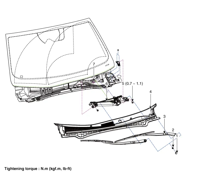
| 1. Cap 2. Nut 3. Wiper arm & blade 4. Cowl top cover | 5. Bolt 6. Wiper motor & linkage assembly 7. Wiper motor connector |
Repair procedures
| Removal |
| 1. | Disconnect the negative (-) battery terminal. |
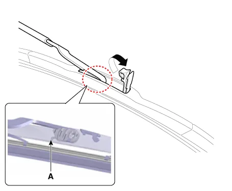
| 2. | If necessary, release the wiper blade fixing clip by pulling up and remove the wiper blade from the inside radius of wiper arm.
|
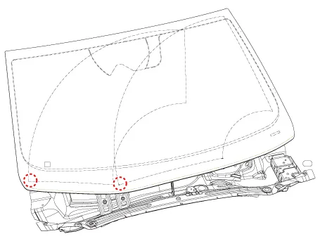
| 3. | Remove the cowl top cover. (Refer to Body - "Cowl Top Cover") |
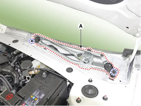
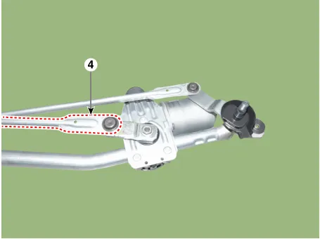
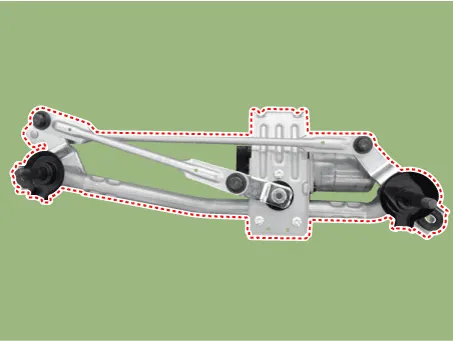
| 4. | Remove the windshield wiper motor and linkage assembly (A) after removing 2 bolts.
|
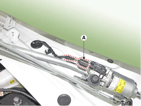
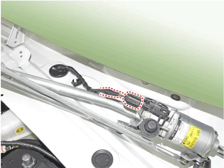
| 5. | Disconnect the wiper motor connector (A) from the wiper motor & linkage assembly.
|
| 6. | Hold the wiper motor crank arm and remove the upper linkage (A) from the wiper motor crank arm.
|

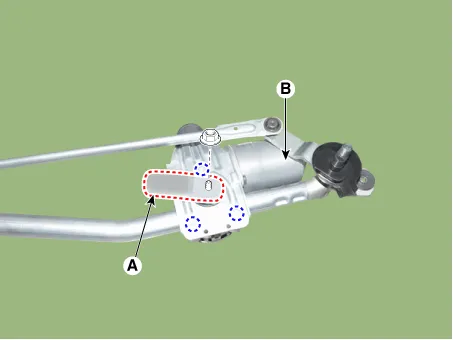
| 7. | Loosen the mounting nut, screws and remove the crank arm (A) and wiper motor (B).
|
| Installation |
| 1. | Install the wiper motor and linkage assembly and then connect the wiper motor connector.
|
| 2. | Install the crank arm.
|
| 3. | Install the cowl top cover. |
| 4. | Install the windshield wiper arm and blade.
|

| 5. | Install the wiper arm and blade to the specified position.
|
| Inspection |
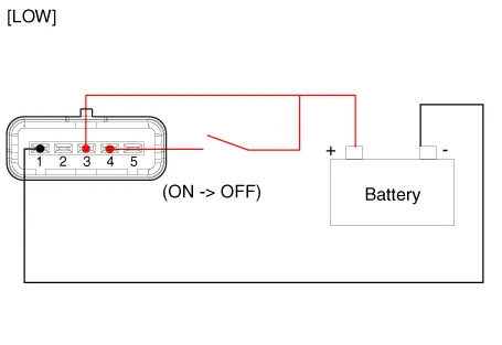
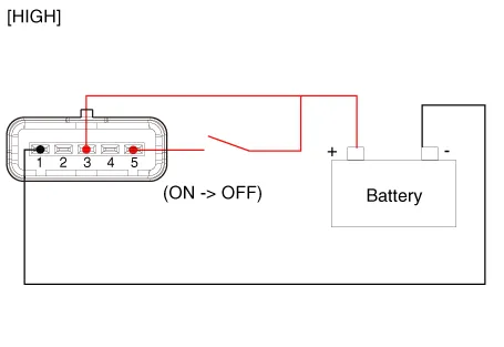
| 1. | Remove the connector from the wiper motor.
|
| 2. | Attach the positive (+) lead from the battery to terminal 3 and the negative (-) lead to terminal 5.
|
| 1. | In the body electrical system, failure can be quickly diagnosed by using the vehicle diagnostic system (Diagnostic tool). The diagnostic system (Diagnostic tool) provides the following information.
|
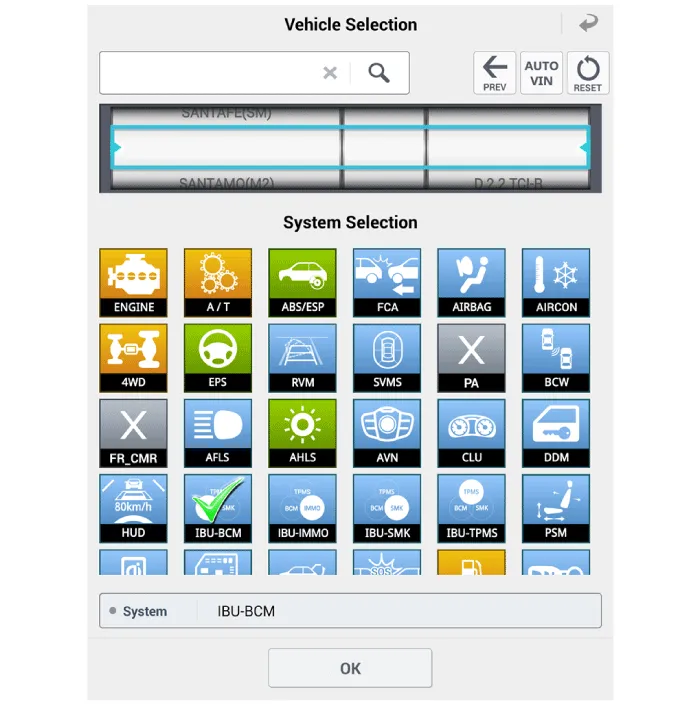
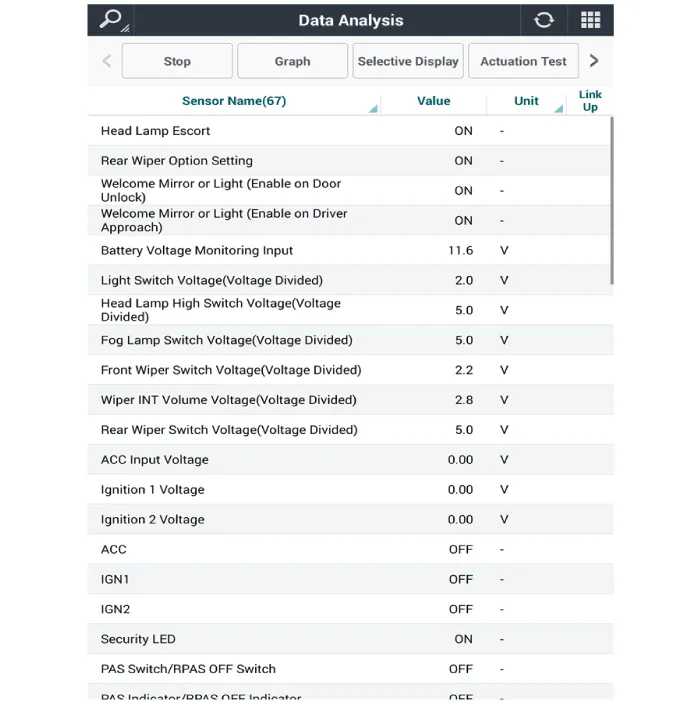
| 2. | If diagnose the vehicle by Diagnostic tool, select "DTC Analysis" and "Vehicle".
|
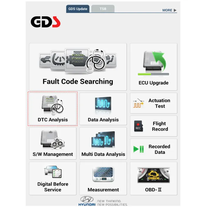
| 3. | Select the 'Data Analysis'.
|

| 4. | Select the 'IBU_BCM' to search the current state of the input/output data.
|
Repair procedures Removal1.Disconnect the negative (-) battery terminal.2.If it is necessary to remove multifunction switch assembly, remove the steering wheel.
Repair procedures InspectionFront Washer Motor1.With the washer motor connected to the reservoir tank, fill the reservoir tank with water. • Before filling the reservoir tank with water, check the filter for foreign material or contamination.
Other information:
Hyundai Elantra (CN7) 2021-2026 Service Manual: Photo Sensor
Description and operation Description 1.The photo sensor is located at the center of the defrost nozzles.2.The photo sensor contains a photovoltaic (sensitive to sunlight) diode. The solar radiation received by its light receiving portion, generates an electromotive force in proportion to the amount of radiation received which is transferred to
Hyundai Elantra (CN7) 2021-2026 Service Manual: Parking Collision-Avoidance Assist (PCA)
Components and components location Components and Components Location Schematic diagrams Schematic DiagramsParking Collision-Avoidance Assist (PCA) Ultrasonic sensorParking Collision-Avoidance Assist (PCA) Rear view camera Repair procedures RemovalParking Collision-Avoidance Assist (PCA) Unit1.
Categories
- Manuals Home
- Hyundai Elantra Owners Manual
- Hyundai Elantra Service Manual
- Instrument Panel Overview
- Components and components location
- Auto Hold. Warning messages
- New on site
- Most important about car
