Hyundai Elantra (CN7): Fuel Delivery System / Fuel Tank
Repair procedures
| Removal |
| 1. | Release the residual pressure in fuel line. (Refer to Fuel Delivery System - "Release Residual Pressure in Fuel Line") |
| 2. | Turn ignition switch OFF and disconnect the negative (-) battery cable. |
| 3. | Remove the rear seat. (Refer to Body - "Rear Seat Assembly") |
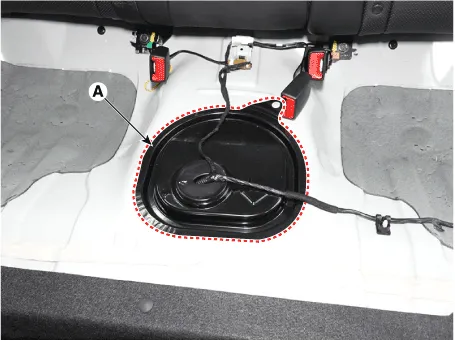
| 4. | Remove the fuel pump service cover (A).
|
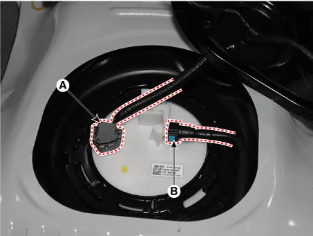
| 5. | Disconnect the fuel pump connector (A). |
| 6. | Disconnect the fuel feed tube quick-connector (B).
|
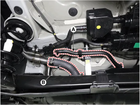
| 7. | Disconnect the leveling hose (A). |
| 8. | Disconnect the fuel filler hose (B).
|
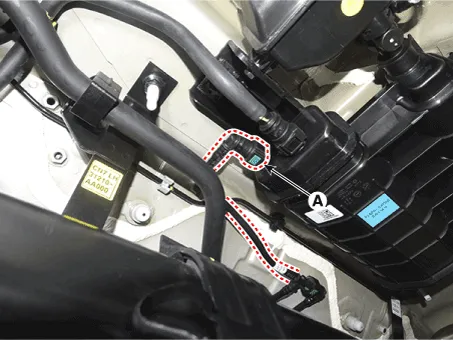
| 9. | Disconnect the vapor hose quick-connector (A)
|
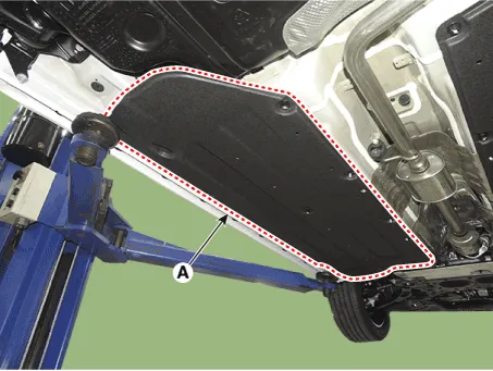
| 10. | Remove the floor under cover (A).
|
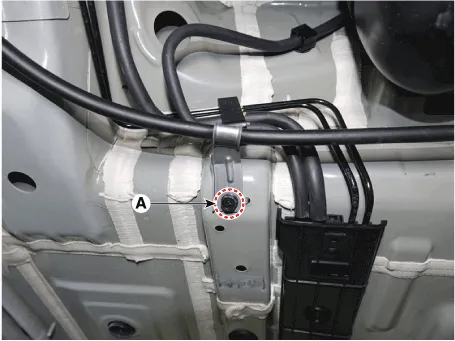
| 11. | Separate the brake line after removing the bracket mounting bolt (A).
|
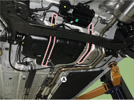
| 12. | Remove the fuel tank band (A).
|

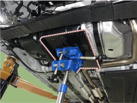
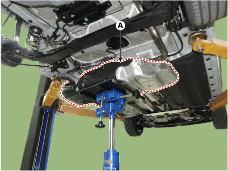
| 13. | Remove the fuel tank (A).
|
| Installation |
| 1. | Install in the reverse order of removal. |
Release Residual Pressure in Fuel Line • There may be some residual pressure even after "Release Residual Pressure in Fuel Line" work, so cover the hose connection with a shop towel to prevent residual fuel from spilling out before disconnecting any fuel connection.
Repair procedures Inspection[Fuel Pump]1.Turn ignition switch OFF and disconnect the negative (-) battery cable.2.Remove the fuel pump assembly.3.Check motor operation by fuel pump connector (A) connecting power (No.
Other information:
Hyundai Elantra (CN7) 2021-2026 Service Manual: Heater & A/C Control Unit (DATC)
Components and components location Components[This illustration shows the LHD type. RHD type is symmetrical.][Connector A] Pin No Function Pin No Function 1Battery9IGN22ILL+ (TAIL)10ISG Battery (+)3-11IGN14LIN BUS12HTD5-13-6-14-7-15-8RHEO (
Hyundai Elantra (CN7) 2021-2026 Service Manual: Front Radar Unit
Components and components location Components Location1. Front rader unit Specifications Specification Item Specification Power supply (V)12Operation voltage (V)9 - 16 Schematic diagrams Circuit DiagramTerminal function Pin No Te
Categories
- Manuals Home
- Hyundai Elantra Owners Manual
- Hyundai Elantra Service Manual
- Body Electrical System
- Driver assistance system
- Vehicle Information
- New on site
- Most important about car
