Hyundai Elantra (CN7): Fuel Delivery System / Fuel Pump
Repair procedures
| Inspection |
| 1. | Turn ignition switch OFF and disconnect the negative (-) battery cable. |
| 2. | Remove the fuel pump assembly. |
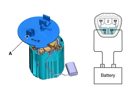
| 3. | Check motor operation by fuel pump connector (A) connecting power (No.4) and ground (No.5).
|
| 1. | Turn ignition switch OFF and disconnect the negative (-) battery cable. |
| 2. | Remove the fuel pump assembly. |
| 3. | Using an ohmmeter, measure the resistance between terminals 1 and 3 of sender connector (A) at each float level.
|
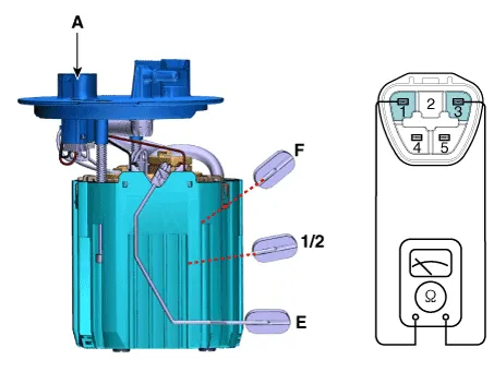
| 4. | Also check that the resistance changes smoothly when the float is moved from "E" to "F".
|
| Removal |
| 1. | Turn the ignition switch OFF and disconnect the battery (-) terminal. |
| 2. | Release the residual pressure in fuel line. (Refer to Fuel Delivery System - "Release Residual Pressure in Fuel Line") |
| 3. | Remove the rear seat. (Refer to Body (Interior and Exterior) - "Rear Seat Assembly") |
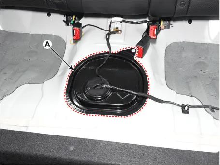
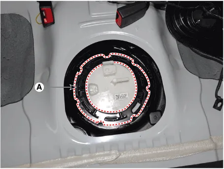
| 4. | Remove the fuel pump service cover (A).
|
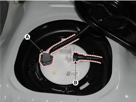
| 5. | Disconnect the fuel pump connector (A). |
| 6. | Disconnect the fuel feed tube quick-connector (B).
|
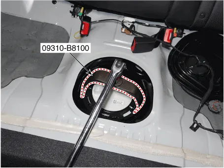
| 7. | Remove the locking ring (A) by using the special service tool [No. : 09310-B8100].
|

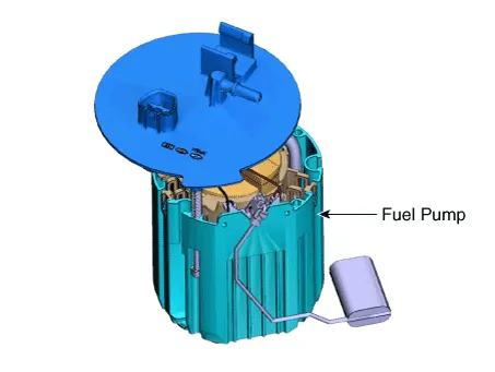
| 8. | Remove the fuel pump from the fuel tank.
|
| Installation |
| 1. | Install in the reverse order of removal.
|

Repair procedures Removal1.Release the residual pressure in fuel line.(Refer to Fuel Delivery System - "Release Residual Pressure in Fuel Line")2.Turn ignition switch OFF and disconnect the negative (-) battery cable.
Repair procedures Removal1.Remove the fuel pump. (Refer to Fuel Delivery System - "Fuel Pump")2.Disconnect the fuel pump motor connector (A) and fuel sender connector (B).
Other information:
Hyundai Elantra (CN7) 2021-2026 Service Manual: General safety information and caution
Instructions (R-134a)When Handling Refrigerant1.R-134a liquid refrigerant is highly volatile. A drop on the skin of your hand could result in localized frostbite. When handling the refrigerant, be sure to wear gloves. 2.It is standard practice to wear goggles or glasses to protect your eyes, and gloves to protect your hands.
Hyundai Elantra (CN7) 2021-2026 Service Manual: A/C Pressure Transducer
Description and operation DescriptionThe A/C Pressure Transducer (APT) converts the pressure value of high pressure line into voltage value after measuring it. By converted voltage value, engine ECU controls the cooling fan by operating it high speed or low speed.
Categories
- Manuals Home
- Hyundai Elantra Owners Manual
- Hyundai Elantra Service Manual
- Front Bumper
- Steering System
- Auto Hold. Warning messages
- New on site
- Most important about car
