Hyundai Elantra (CN7): Auto Lighting Control System / Auto Light Sensor
Hyundai Elantra (CN7) 2021-2025 Service Manual / Body Electrical System / Auto Lighting Control System / Auto Light Sensor
Repair procedures
| Inspection |
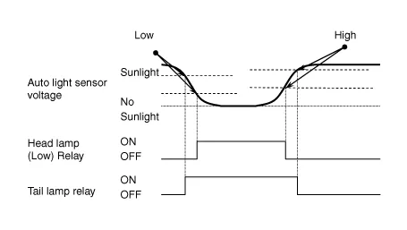
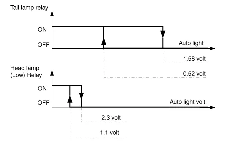
Check if the auto light control operates like a timing chart shown below. Tail lamp output and head lamp (Low) output is controlled based on the auto light sensor's input (illumination intensity) when the Auto Light Switch in Multi-Function Switch is turned ON, and the vehicle is in IGN1 or IGN2 ON Mode. If IGN1 = ON, BCM detects this voltage, and if the voltage exceeds rated voltage, then auto light failure occurs. (below 4V or above 6V)
|

In the state of IGN1 ON, when multi function switch module detects auto light switch on, tail lamp relay output and head lamp low relay output are controlled according to auto light sensor's input.The auto light control doesn't work if the pin sunlight supply (5V regulated power from Ignition 1 power to sunlight sensor) is in short circuit with the ground.If IGN1 ON, The BCM monitors the range of this supply and raises up a failure as soon as the supply’s voltage is out of range. Then this failure occurs and as long as this is present, the head lamp must be turned on without taking care about the sunlight level provided by the sensor.This is designed to prevent any head lamp cut off when the failure occurs during the night.
| Removal |
|
| 1. | Disconnect the negative ( - ) battery terminal. |
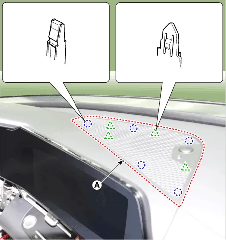
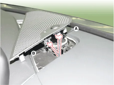
| 2. | Using a remover and remove the crash pad center speaker grille (A).
|
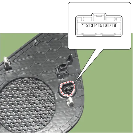
| 3. | Disconnect the auto light sensor connector (A) and security sensor connector (B).
|
| Installation |
| 1. | Connect the auto light sensor connector and security sensor connector. |
| 2. | Install the crash pad center speaker grille. |
Circuit Diagram
Other information:
Hyundai Elantra (CN7) 2021-2025 Service Manual: Immobilizer Control Unit
Components and components location Components (1)With Smart KeyConnector Pin Information Pin no Connector A Connector B Connector C Connector D Connector E 1ESCL
Hyundai Elantra (CN7) 2021-2025 Service Manual: Components and components location
C
Categories
- Manuals Home
- Hyundai Elantra Owners Manual
- Hyundai Elantra Service Manual
- Front Bumper Assembly
- Drive Mode
- Towing
- New on site
- Most important about car

Copyright © 2025 www.helantra7.com - 0.015