Hyundai Elantra (CN7): Body Electrical System / Auto Lighting Control System
Description and operation
| Description |
| 1. | Do not add another device on top of this device. |
| 2. | Be sure to switch to manual during poor visibility climate, such as fog, heavy rain, or cloudy weather. |
| 3. | Illumination intensity in an actual vehicle is not always constant, and lamp ON/OFF time may very depending on the climate, season, and surrounding environment. |
| 4. | Use this system only during sunrise and sunset period, and manually control lamp ON/OFF for general conditions. |
| 5. | Error may occur if light block coating that may change interior illumination is applied. |
Components and components location
| Component Location |
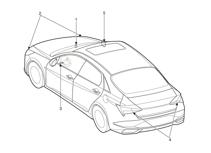
| 1. Auto light sensor 2. Head lamps 3. Lighting switch (Auto) | 4. Rear combination lamps 5. Integrated body control unit (IBU) |
Specifications
| Specifications |
|
Items
|
Specifications
| |
| Rated voltage | 5V | |
| Load | Max. 1mA (Relay load) | |
| Illuminations (LUX) | 100 | 0.76 ± 0.17V |
| 150 | 1.3 ± 0.30V | |
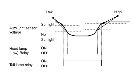
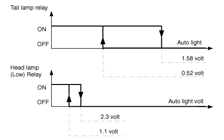
Schematic diagrams
| Circuit Diagram |
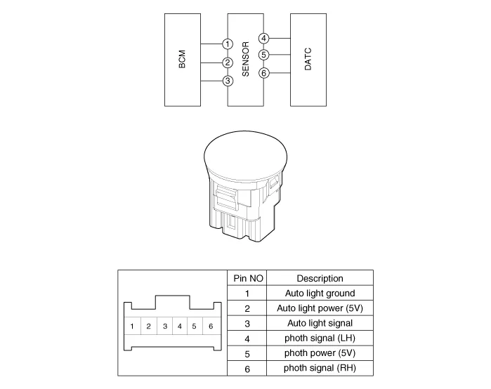
Auto Light Sensor
Repair procedures
| Inspection |
|

| Removal |
|
| 1. | Disconnect the negative ( - ) battery terminal. |
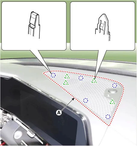
| 2. | Using a remover and remove the crash pad center speaker grille (A).
|
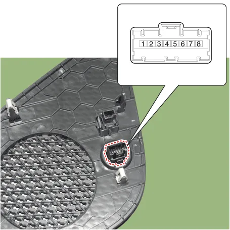
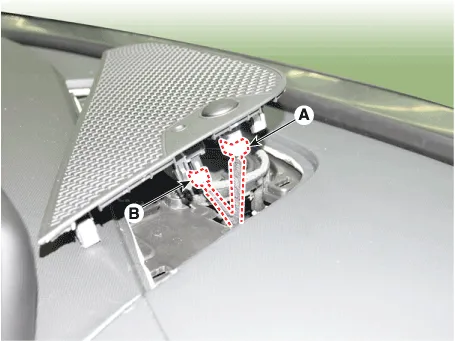
| 3. | Disconnect the auto light sensor connector (A) and security sensor connector (B).
|
| Installation |
| 1. | Connect the auto light sensor connector and security sensor connector. |
| 2. | Install the crash pad center speaker grille. |
Repair procedures RemovalMood lamp unit1.Disconnect the negative (-) battery terminal.2.Remove the main crash pad assembly.(Refer to Body - "Main Crash Pad Assembly")3.
Components and components location Component Location1. Head lamp leveling actuator2. Head lamp leveling switch Head Lamp Leveling Switch Schematic diagrams Schematic Diagrams Repair procedures Replacement1.
Other information:
Hyundai Elantra (CN7) 2021-2026 Service Manual: Specifications
SpecificationAir Conditioner Item Specification CompressorTypeGamma 1.6 MPI, Gasoline 2.0 NU MPI, Gasoline 1.6 T-GDI : 6HVx14Gasoline 1.6 MPI : 6HVe14Oil type & CapacityFD46XG (IDEMITSU) 100 ± 10 g Pulley type6PK-TYPEDisplacement145 cc/revExpansion valveTypeBlock type RefrigerantTypeR - 134
Hyundai Elantra (CN7) 2021-2026 Service Manual: Ambient Temperature Sensor
Description and operation DescriptionThe ambient temperature sensor is located at the front of the condenser and detects ambient air temperature. It is a negative type thermistor; resistance will increase with lower temperature, and decrease with higher temperature.
Categories
- Manuals Home
- Hyundai Elantra Owners Manual
- Hyundai Elantra Service Manual
- Maintenance
- Brake System
- General Tightening Torque Table. General information
- New on site
- Most important about car
