Hyundai Elantra (CN7): Body Electrical System / Head Lamp Leveling Device
Hyundai Elantra (CN7) 2021-2026 Service Manual / Body Electrical System / Head Lamp Leveling Device
Components and components location
| Component Location |
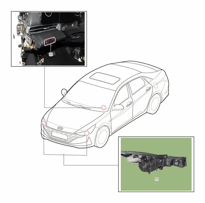
| 1. Head lamp leveling actuator | 2. Head lamp leveling switch |
Head Lamp Leveling Switch
Schematic diagrams
| Schematic Diagrams |

Repair procedures
| Replacement |
| 1. | Disconnect the negative (-) battery terminal. |
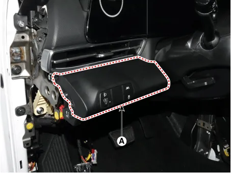
| 2. | Remove the crash pad lower panel (A). (Refer to Body - "Crash Pad Lower Panel") |
| 3. | Loosen the mounting screw and remove the crash pad lower switch (A).
|
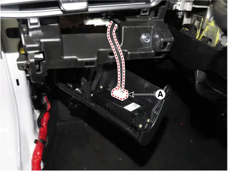
| 4. | Disconnect the crash pad lower switch connector (A).
|
| 5. | To install, reverse the removal procedure. |
Description and operation DescriptionIt's a system that uses illumination sensor to automatically turn ON the tail lamp and head lamp based on the change in surrounding environment's illumination condition.
Other information:
Hyundai Elantra (CN7) 2021-2026 Service Manual: Components and components location
C
Hyundai Elantra (CN7) 2021-2026 Service Manual: Ignition Switch Assembly. Repair procedures
Repair procedures Replacement1.Disconnect the negative (-) battery terminal.2.Remove the crash pad lower panel.(Refer to Body - "Crash Pad")3.Remove the steering column upper & Lower shroud.4.Remove the ignition switch and disconnecting the Key Warning / immobilizer connector.
Categories
- Manuals Home
- Hyundai Elantra Owners Manual
- Hyundai Elantra Service Manual
- Auto Hold. Warning messages
- Specifications
- Vehicle Information
- New on site
- Most important about car

Copyright © 2026 www.helantra7.com - 0.0158