Hyundai Elantra (CN7): Steering Wheel (Heated Steering Wheel) / Heated Steering Wheel Switch
Description and operation
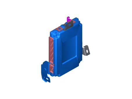
| Description |
| 1. | Heated Control Unit (Integrated Body Control Unit (IBU))
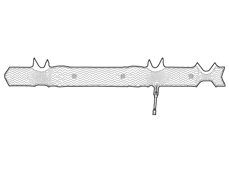
Heated pad
|
Components and components location
| Compoents Location |
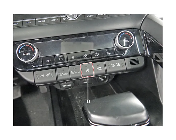
| 1. Heated steering wheel switch |
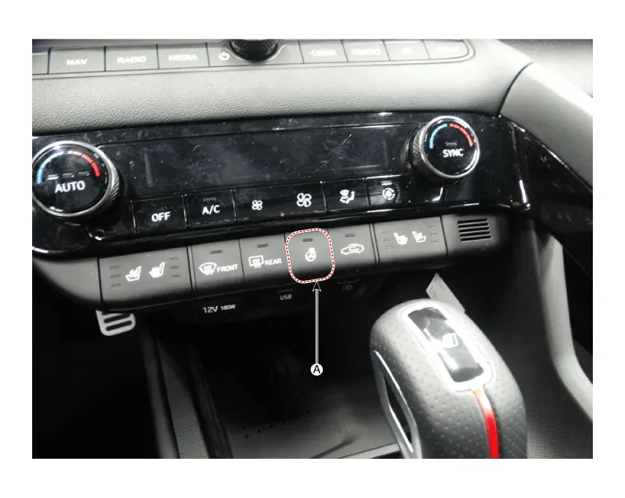
| 1. Heated steering wheel switch |
Specifications
| Specifications |
|
Item
|
Specification
|
| Voltage | 13.5 V |
| Heated pad resistance | 1.5 - 1.9 Ω [22°C (71.6°F)] |
| NTC resistance | 9.70 - 10.3 kΩ |
Repair procedures
| Removal |
| 1. | Disconnect the negative (-) battery terminal. |
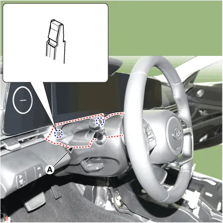
| 2. | Remove the steering column shroud upper panel (A) by using the screw driver or remover. [G 1.6 MPI / LPI]
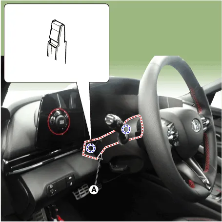
[G 1.6 T-GDI]
|
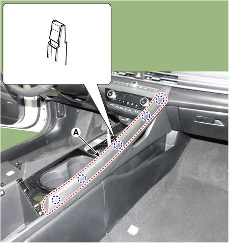
| 3. | Remove the floor console side garnish (A) by using the screw driver or remover.
|
| 4. | Remove the crash pad garnish [CTR] (A) by using the screw driver or remover.
|
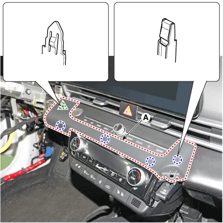
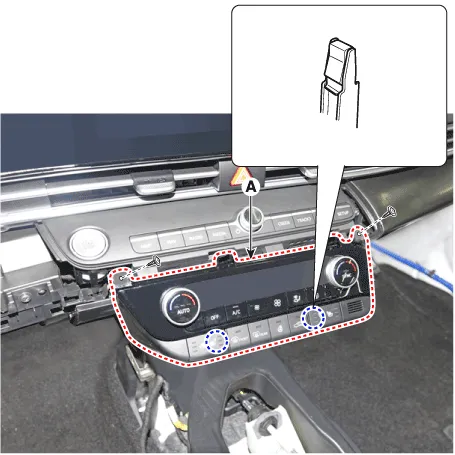
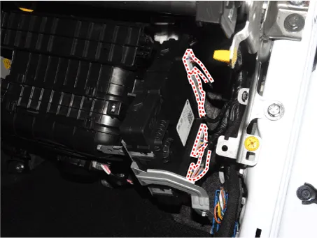
| 5. | Remove the heater and heated steering switch (A) after loosening the screw.
|
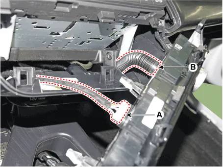
| 6. | Disconnect the connector (A) and hose (B) after pushing the lock pin.
|
| 1. | Disconnect the negative (-) battery terminal. |
| 2. | Remove the glove box upper cover. (Refer to Body - "Glove Box Upper Cover Assembly") |
| 3. | Remove the IBU (A) after loosening the mounting nuts and bolt.
|
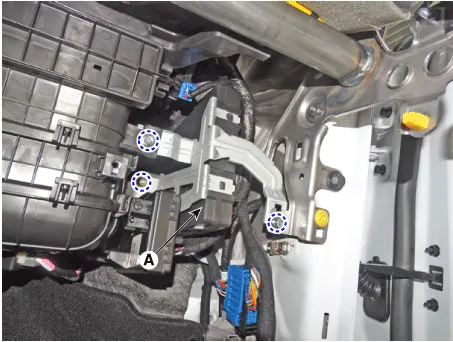
| 4. | Remove the IBU after disconnecting the connector.
|
| Inspection |
| 1. | Measure a resistance of NTC and Heated pad.
|
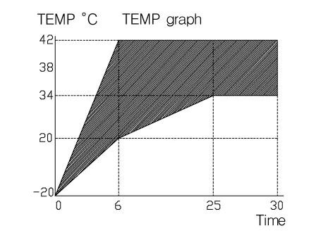
| 2. | Measure a temperature.
|
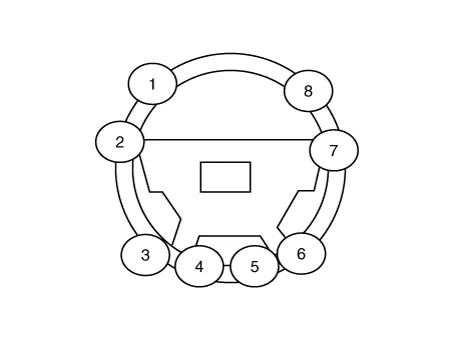
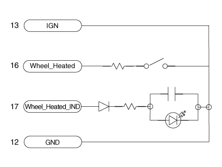
| 3. | Check for continuity between the terminals in each heated steering switch.
|
| Installation |
| 1. | To install, reverse the removal procedure. |
Removal1.Turn the ignition switch OFF and disconnect the battery negative (-) cable.2.Turn the steering wheel so that the front wheels can face straight ahead.
Other information:
Hyundai Elantra (CN7) 2021-2026 Service Manual: High Mounted Stop Lamp
Repair procedures Removal1.Disconnect the negative (-) battery terminal.2.Remove the rear package tray trim.(Refer to Body - "Rear Package Tray Trim")3.Loosen the mounting screws and remove the high mounted stop lamp (A).Installation1.Install the high mounted stop lamp.
Hyundai Elantra (CN7) 2021-2026 Service Manual: Heater & A/C Control Unit (DATC)
Components and components location Components[This illustration shows the LHD type. RHD type is symmetrical.][Connector A] Pin No Function Pin No Function 1Battery9IGN22ILL+ (TAIL)10ISG Battery (+)3-11IGN14LIN BUS12HTD5-13-6-14-7-15-8RHEO (
Categories
- Manuals Home
- Hyundai Elantra Owners Manual
- Hyundai Elantra Service Manual
- Front Radar Unit
- Function settings
- Auto Hold. Warning messages
- New on site
- Most important about car
